Ian KD8CEC is working on a protocol to allow Nextion LCD touch displays to communicate with the µBITx.
He is implementing this a little differently to most support for Nextion LCDs.
The firmware will handle communication between the uBITX arduino and Nextion LCD using template files.
There are quite a few variables in the Nextion LCD. If the status of any parameters in the uBITX changes, the variables sent to the Nextion LCD will also be changed at the same time (and vice-versa). This should allow any Nextion display and any configuration of the display’s User Interface to interact with the µBITx. This means constructors can customise their µBITx display using the Windows GUI used with the Nextion to configure the “look and feel”.
For example, when uBITX’s frequency changes, it is transferred to a specific variable on Nextion LCD.
Example code
Below is an example of simple frequency and mode display changes
Ian KD8CEC has formally released version 1.08 of his firmware. This the first major release since 1.061, although there have been a number of Beta versions in between that many constructors will have donwloaded.
Some key features in this version include:
1.Receive performance is improved compared to the original firmware or version 1.061
2.ATT function has been added to reduce RF gain (This shifts the 45Mhz IF passband down the slope of the filter giving an attenuator effect).
3.Added the ability to connect an inboard or outboard SDR unit after the 45MHz roofing filter (A low cost RTL-SDR is available that can be controlled by computer software providing a full SDR receiver)
4.Added ADC Monitoring in CAT communications
5. Supports several LCD variants including:
16×02 Parallel LCD – i.e. LCD equipped with µBITX
the 16×02 LCD display configured to use I2C
20×04 Parallel LCD with existing wiring in the µBITx
20×04 LCD display configured to use I2C
Two 16×02 LCD displays configured to use I2C (Dual LCD mode)
6.Added extended switch support (up to 6 switches can be incorporated on your front panel to control various rig functions).
7. S Meter support – Any S-meter should be compatible. The S-Meter will work on 2 or 4 line displays.
8.Added S-Meter Setting Assistant to uBITX Manager
You can download HEX file and uBITX Manager from the link above. You can also download the source code at https://github.com/phdlee/ubitx and see all the changes I’ve made so far. If there is a non-critical bug in the public version, Ian will link to the new firmware from his blog.
A new version of the CEC firmware manual is anticipated shortly.
Ian KD8CEC’s test firmware supported extended extended buttons in Version 1.072 and this feature continues in the latest BETA release version 1.073.
Ian received from the beta testers to make the extended key (push button functions) a bit more flexible. He changed the feature to allow up to six pushbuttons (previously the maximum was four buttons) and functions that are allocated to buttons can now be selected by the user.
Description of changes
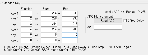
In uBITX Manager V1.04, up to 6 expansion keys (pushbutton keys) can be set as follows.
You need to set the role for the ‘Function’ item.
Function settings currently able to be controlled by buttons include:
0:None
1:Mode Select
2:Band Up
3:Band Down
4:Tune Step
5:VFO A/B Toggle
6:Split On/Off
7:TX On/Off
8:SDR Mode On/Off
9:RIT On/Off
In the above example, Button 1 is Mode Select, Button 2 is Band Up, Button 3 is Band Down, and Button 4 is Tune Step.
If you are a frequent CW practitioner, you can use the TX On / Off button as shown below:
Users may also want to turn off the transmit function by pressing button 4 during CW practice. At the end of the CW practice exercise, pressing button 4 would again activate the transmit function.
If you are a frequent user of SDR, you can probably set it up like this:
Since the Mode select function is not very important in SDR, a VFOA / VFO B toggle switch and SDR On / Off switch may be mapped instead.
As mentioned in the previous article, resistors can be any value (but keep them apart). Ian recommends you use resistor values over 100K (with values less than this reserved for later use cases).
Mike ZL1AXG found that resistor values greater than 500K were too close to the residual value sensed by the arduino analogue pin and caused the software to be unstable. Choose values between 100k and 500k.
KD8CEC Firmware Version 1.073 will be released within a day or two when testing is complete. You can download it right now and use it, but it may be further modified before final release.
Ian KD8CEC, in uBITX Firmware CEC Version 1.073 Beta, is supporting the use of up to 4 additional front-panel switches to control a range of functions normally only accessible via the menu system.
Preparations for adding additional function switches
Step 1: You will need four push switches and four resistors.
The value of the resistors is not particularly important, but a spread of resistance values is helpful. Ian recommends that the value of each resistance exceeds 100k ohms. This will allow the addition of more switches at a later date.
Ian uses 470k, 330k, 200k, and 150k in his example.
Step 2: Identify the wires on your function switch
Your rotary encoder will probably have a red wire and a yellow wire currently connected to the switch (not the three way connector on the encoder, but the two way connector). These wires connect to Pin 4 and Pin 5 of the raduino connector respectively.
When you press the function switch on the rotary encoder the red wire (which connects to an analogue input on the arduino nano) becomes grounded to the yellow wire.
3. Install your switches and connect up resistors in series with the switches
Install up to four switches with connections paralleled with the encoder switch. One side of each switch should be connected to the red wire on the encoder switch. The other side of each switch should be connected to a resistor that is in turn connected to the yellow wire on the encoder as illustrated in the photo below.
All resistors should be of a different value. A good starting point would be the values that Ian used, but if you don’t have these in the junk box, choose values you do have – as separated in value as possible.
4.Setting the switch values in the KD8CEC firmware.
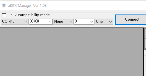
You now need to save the switch information in Ian’s uBITX firmware. To do this you need to have installed and run the KD8CEC uBITX Manager software. This runs on virtually any version of Windows, and on Linux. See Ian’s website for further details. and to download the current version of uBITx manager.
Extended switch settings are supported in uBITX Manager Version 1.03 or later. Go through the following steps:
A) Connect -> Read
B) ‘Decode =>’ -> Scroll down
You will see a screen that manages the ‘Extended Key’ as shown below.
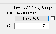
C) Press the Read ADC button.
It will probably have a value of around 254. This is the Analogue to Digital conversion value being read by the Arduino Nano on Analogue Pin A6 to which the function key is connected and then divided by 4.
The reason for dividing by 4 is to reduce the number of bytes required for storage of the value in EEPROM. Accuracy of the analogue read means that greater precision is unnecessary.
Setting the mode button value
You should now measure the value when you press a button. Click ‘Read ADC’ while holding the switch you have chosen to be used as ‘Select Mode’.
Try one or two more times and average your results.
Enter the measured value into the ‘Mode’ value on the left.
Ian connected a 470k resistor to the ‘Select Mode’ switch, so the ADC result was 235. He set the range to -1 to +1 to prevent the switch from malfunctioning.
The values vary depending on the resistance you have used, the state of the switch, and the length of the cable.
Enter values for Band Up, Band down and Tune Step functions
In this way, enter values for the ‘Band Up’, ‘Band Down’ and ‘Tune Step’ switches
At the end of this process you should have something like this in the table in uBITx Manager:
If the switch is not installed (i.e. it is free floating while you try out this concept) it may be difficult to click on the ‘Read ADC’ at the same time as holding down the switch. In this case, select ‘5 Sec Delay’ and click the ‘Read ADC’ button to see the count down:
When you have finished setting up the ADC ranges for each switch, you should select “encode” and then write the data to the µBITx. Reboot your µBITx and you should now have four new switches on your front panel to avoid having to delve into the menu system to control everything on your rig.
Below is the link to a video that Ian has provided to help illustrate how to wire up the switches and set the ADC values in uBITx Manager.
Ian KD8CEC has released version 1.072 firmware. This includes support for both 20×4 and the standard 16×2 LCD screens (using i2c). It enables constructors to include or remove bits of code, and it allows the integration of an US$8 RTL-SDR to work on all HF bands to give full DSP, waterfall display, etc.
Ian KD8CEC is working on a new release of his CEC firmware for the uBITx that will be more modular in approach (picking up on John VK2ETA’s mods to Ian’s firmware), interface with a range of displays (I2C versions of the 1602 and 2004 displays as well as the display that comes with the Raduino). More importantly, however, this new version will enable the µBITx front-end of the receiver to be connected to an RTL-SDR USB device. The RTL-SDR device will draw on the HF receive sensitivity of the µBITx along with the front end bandpass filter and first IF roofing filter and associated IF stage amplifier (normally at 12MHz) to produce a quality SDR receiver (for just a few $s invested in the RTL-SDR tuner).
This version is available to download (1.071 Beta) from Ian’s website now.
Ian KD8CEC has released Version 1.061 of his µBITx firmware. You can read more about it here. This version provides support for WSPR and has several bug fixes.
Ian KD8CEC has released version 1.061 of his KD8CEC Firmware for the µBITx. This adds the WSPR mode to your µBITx. If you use Ian’s uBITX Manager to put WSPR information into uBITX (using your PC), the µBITX no longer needs any external device to transmit WSPR.
Ian says, “Beta testers have been very helpful when embedding the WSPR functionality. WSPR mode will continue to improve in the future.
“By using WSPR before or after having a QSO, you can check where your uBITX is getting to around the world.”
Added or improved in version 1.061:
1.Added WSPR function to uBITX
Update uBITX Manager to Version 1.0
Reduced program size
Fixed IF Shift Bug
Other bugs fixed
CWL, CWU mode are more friendly. Two options are displayed for shifting frequency.
Ian Lee, KD8CEC, has released a new (Beta) version of his µBITX Firmware CEC Version 1.04. This version adds the WSPR TX mode. It still needs wider testing before a release version is posted. Ian is looking for beta testers who have a µBITX, can install his firmware and his PC Software – uBITx Manager that allows for easy configuration of firmware settings, and know how to use WSPR.
The WSPR function has been squeezed into the small programming space of the µBITX (32Mb) including the station callsign, location(2alpha, 2 number), dB and frequency information to be used for transmission.
As a field portable unit, you only need to bring the µBITX and antenna to transmit WSPR as all information is already contained in the rig (no computer is required). You do not need to make any modifications to your uBITX to use WSPR.
Ian Lee, KD8CEC, has released a further minor update of his firmware (v1.04). You can download it here.
The changes since version 1.01 are as follows:
– Reduce cpu usage
– Change BFO Calibration step (50Hz to 5Hz steps)
– Change CW Frequency Display (frequency is more accurate when in CWL, CWU Mode)
– Optimized source code and reduced program size (97% -> 95%)