Ian KD8CEC’s test firmware supported extended extended buttons in Version 1.072 and this feature continues in the latest BETA release version 1.073.
Ian received from the beta testers to make the extended key (push button functions) a bit more flexible. He changed the feature to allow up to six pushbuttons (previously the maximum was four buttons) and functions that are allocated to buttons can now be selected by the user.
Description of changes
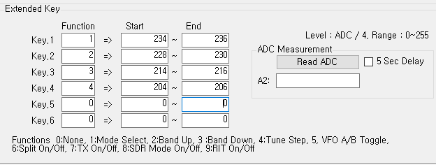
In uBITX Manager V1.04, up to 6 expansion keys (pushbutton keys) can be set as follows.
You need to set the role for the ‘Function’ item.
Function settings currently able to be controlled by buttons include:
0:None
1:Mode Select
2:Band Up
3:Band Down
4:Tune Step
5:VFO A/B Toggle
6:Split On/Off
7:TX On/Off
8:SDR Mode On/Off
9:RIT On/Off
In the above example, Button 1 is Mode Select, Button 2 is Band Up, Button 3 is Band Down, and Button 4 is Tune Step.
If you are a frequent CW practitioner, you can use the TX On / Off button as shown below:
Users may also want to turn off the transmit function by pressing button 4 during CW practice. At the end of the CW practice exercise, pressing button 4 would again activate the transmit function.
If you are a frequent user of SDR, you can probably set it up like this:
Since the Mode select function is not very important in SDR, a VFOA / VFO B toggle switch and SDR On / Off switch may be mapped instead.
As mentioned in the previous article, resistors can be any value (but keep them apart). Ian recommends you use resistor values over 100K (with values less than this reserved for later use cases).
Mike ZL1AXG found that resistor values greater than 500K were too close to the residual value sensed by the arduino analogue pin and caused the software to be unstable. Choose values between 100k and 500k.
KD8CEC Firmware Version 1.073 will be released within a day or two when testing is complete. You can download it right now and use it, but it may be further modified before final release.
Ian KD8CEC, in uBITX Firmware CEC Version 1.073 Beta, is supporting the use of up to 4 additional front-panel switches to control a range of functions normally only accessible via the menu system.
Preparations for adding additional function switches
Step 1: You will need four push switches and four resistors.
The value of the resistors is not particularly important, but a spread of resistance values is helpful. Ian recommends that the value of each resistance exceeds 100k ohms. This will allow the addition of more switches at a later date.
Ian uses 470k, 330k, 200k, and 150k in his example.
Step 2: Identify the wires on your function switch
Your rotary encoder will probably have a red wire and a yellow wire currently connected to the switch (not the three way connector on the encoder, but the two way connector). These wires connect to Pin 4 and Pin 5 of the raduino connector respectively.
When you press the function switch on the rotary encoder the red wire (which connects to an analogue input on the arduino nano) becomes grounded to the yellow wire.
3. Install your switches and connect up resistors in series with the switches
Install up to four switches with connections paralleled with the encoder switch. One side of each switch should be connected to the red wire on the encoder switch. The other side of each switch should be connected to a resistor that is in turn connected to the yellow wire on the encoder as illustrated in the photo below.
All resistors should be of a different value. A good starting point would be the values that Ian used, but if you don’t have these in the junk box, choose values you do have – as separated in value as possible.
4.Setting the switch values in the KD8CEC firmware.
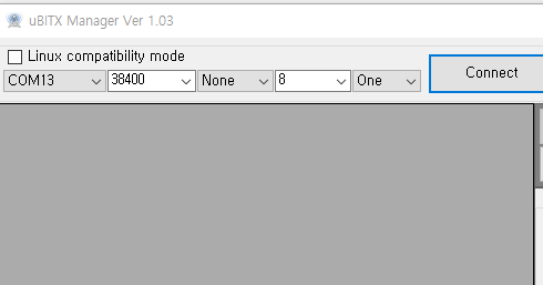
You now need to save the switch information in Ian’s uBITX firmware. To do this you need to have installed and run the KD8CEC uBITX Manager software. This runs on virtually any version of Windows, and on Linux. See Ian’s website for further details. and to download the current version of uBITx manager.
Extended switch settings are supported in uBITX Manager Version 1.03 or later. Go through the following steps:
A) Connect -> Read
B) ‘Decode =>’ -> Scroll down
You will see a screen that manages the ‘Extended Key’ as shown below.
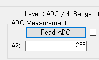
C) Press the Read ADC button.
It will probably have a value of around 254. This is the Analogue to Digital conversion value being read by the Arduino Nano on Analogue Pin A6 to which the function key is connected and then divided by 4.
The reason for dividing by 4 is to reduce the number of bytes required for storage of the value in EEPROM. Accuracy of the analogue read means that greater precision is unnecessary.
Setting the mode button value
You should now measure the value when you press a button. Click ‘Read ADC’ while holding the switch you have chosen to be used as ‘Select Mode’.
Try one or two more times and average your results.
Enter the measured value into the ‘Mode’ value on the left.
Ian connected a 470k resistor to the ‘Select Mode’ switch, so the ADC result was 235. He set the range to -1 to +1 to prevent the switch from malfunctioning.
The values vary depending on the resistance you have used, the state of the switch, and the length of the cable.
Enter values for Band Up, Band down and Tune Step functions
In this way, enter values for the ‘Band Up’, ‘Band Down’ and ‘Tune Step’ switches
At the end of this process you should have something like this in the table in uBITx Manager:
If the switch is not installed (i.e. it is free floating while you try out this concept) it may be difficult to click on the ‘Read ADC’ at the same time as holding down the switch. In this case, select ‘5 Sec Delay’ and click the ‘Read ADC’ button to see the count down:
When you have finished setting up the ADC ranges for each switch, you should select “encode” and then write the data to the µBITx. Reboot your µBITx and you should now have four new switches on your front panel to avoid having to delve into the menu system to control everything on your rig.
Below is the link to a video that Ian has provided to help illustrate how to wire up the switches and set the ADC values in uBITx Manager.
This firmware is targeted at portable and /PM operations. John doesn’t plan to add much in the way of further features unless they are of value to portable operations.
If you want to use sections of code in your projects, follow the #ifdef/#endif segments that mostly enclose the sections of code of interest. John is happy to help with extraction of code if requested.
The software is organised in options that can be enabled/disabled (mostly) independently.
The key features added in this version are:
1. Reduction in libraries size by 1K byte (this allows for more features to be added in the limited memory of the Arduino).
2. Added a “Stock Standard” option for unmodified rigs wired as per HF Signals instructions.
3. Added a two adjustable levels supply voltage monitor with visual and audio indication. Level two will disable TX to protect the battery.
4. Added the WSPR beacon option from KD8CEC software version 1.061.
5. Changed logic for CW modes: frequency displayed is carrier frequency, with Rx frequency shifted up or down (CWL / CWU).
6. In split modes, the VFO A/B label and frequency change when going from Rx to Tx.
7. RIT display: frequency is kept fixed, RIT is now shown as +/- frequency difference.
8. Added ALC levels for MAX level too. Used to be no attenuation.
The second update is part of his approach to continuously look for program size reduction to have as many features as possible concurrently in the Nano’s memory. Inspired by Ian Lee’s KD8CEC version 1.701, he has included a modified version of his TinyLCD library. Compared to the complete default LiquidCrystal library this cut down version saves 452 bytes of program flash memory. He has made this code into an object oriented class so it can be easily retrofitted into other projects as there were only two lines of code to change.
Jim W0EB and Ron W2CTX have released Version 4.00R. This is the I2C release firmware for modified hardware on the display. The W0EB/W2CTX firmware also requires a minor CW keying control mod.
This is a FOUR line display version designed to work with a 4 line by 20 character LCD display that has an I2C “backpack” or, one with the I2C interface built in. As long as you know the I2C address for your display and can properly set that in the .ino source file, it should compile and run on an I2C modified Raduino card as well as on our RadI2Cino card which can be purchased by contacting W0EB (email address on QRZ). Jim Sheldon, W0EB
Ian KD8CEC has released version 1.072 firmware. This includes support for both 20×4 and the standard 16×2 LCD screens (using i2c). It enables constructors to include or remove bits of code, and it allows the integration of an US$8 RTL-SDR to work on all HF bands to give full DSP, waterfall display, etc.
Jim Sheldon – W0EB has released W0EB/W2CTX I2C software Version 4.00R for I2C enabled uBITX Raduino cards and the W0EB/W2CTX/N5IB RadI2CIno cards.
This software will NOT run on a stock standard Raduino card unless it has been modified to operate with an I2C display This version is for an I2C enabled 2 X 16 LCD display. (The 4 line x 20 character version will be released later).
John, VK2ETA, has implemented a range of changes in Ian KD8CEC’s software targeted at portable operations (the software can be downloaded here in the files section of the BITX20 IO Group).
VK2ETA Software modifications to KD8CEC firmware
The scope of these modifications is described below:
Options for various features – These can be turned on or off. Key objective is to be able to customise the rig based on your needs and unfortunately on the restricted memory size of the Nano. So not all features can be selected at once. Choices, choices…
ATU control – A servo-based L-Network ATU. The communication between the Raduino and the ATU Arduino is via I2C. There is a separate sketch for the ATU Arduino (Nano or Pro-mini). ATU operating mode can be set to OFF, Manual as in on-demand, or auto-RX meaning that it pre-tunes based on historical data on a change of band and after first change of dial frequency (for a quick scan of the bands). It uses the EEPROM data of the closest stored frequency for pre-tune or tune on-demand to accelerate the tuning process.
Handsfree microphone/headphone – Using an Android style 3 rings (TTRS) handsfree earpieces/mic combination, with 1 or 3 buttons (Play/Pause, +, -), the PTT is controlled by Play/Pause as toggle, and I use long presses on + and – as respectively pre-tune and smart-tune of the ATU. Short + or – presses could be used for frequency up and down. Requires a very simple hardware mod to free-up A6 (see below).
S-meter measure and display – using analogue input A7 from an 2N7002 based AGC or a MAX9814 circuit or any other for that matter.
Software based AGC range extender – to augment (as in double or triple) the dynamic range of an audio AGC. This uses the slope of the 1st If filter at 45Mhz to attenuate the Rx signal when the audio AGC reaches its limit. Adds over 50dB of dynamic range.
Forward power and SWR measure and display – Currently assumes that the ATU is providing that info over I2C. Otherwise could be adapted with a pair of analogue inputs for measure. See the excellent NT6D design on the wiki.
Options for displaying the S-Meter, SWR and forward power – in either easy to see “fat” bars with no number, or “skinny” bars with more text and numbers.
Enable a “Memory mode” – selectable by menu, which cycles through all the populated memories (channels). Dial lock also locks the change of channels.
Made some rarely used or once-off functions as options – to recover program memory after initial tuning and allow for more options to be selected.
Fixed some issues with the IF-shift option – Ian has resolved these in his new V1.06 and later releases. Two issues were present: IF-shift in USB would change the receive frequency and it was applied to TX as well. Now applies to Rx only.
Hardware modifications required to use VK2ETA software mod
The only required hardware mod is to connect the CW key input to the PTT. Since in Ian’s software we select the mode by menu, there is no need to have a separate analogue input tied-up for the CW key. This frees-up analogue input 6 for use by other functions like the handsfree option above.
Still to come
John plans to apply Ian’s improvements in v1.06, especially the CW transmit frequency option and if possible the WSPR beacon mode (as a further add-in option).
How to use VK2ETA software
Download the zip files, and unzip these in your Arduino sketches folder. Edit the ubitx_20 options sections, using #define for enabled and #undef for disabled.
Perform a CTRL-R to compile and check how much memory is used. If you go over the limit, a warning is issued. Providing you have enough memory to run the software, upload the sketch to the Arduino.
John has uploaded both the Raduino as well as the Arduino sketch for the ATU and SWR measurement. They can be found in the folder “Variations on Ian Lee’s Software (by VK2ETA) + ATU sketch”.
Nigel G4ZAL asked what people saw in KD8CEC’s UBITx Manager for their calibrations.
Nikos, SV1IYF, sent Nigel his settings, and they may be useful for others who want to recalibrate roughly to get going:
Master Calibration 143000 => Accuracy within 3Hz @10MHz, as delivered was ~75Hz off
USB Calibration 11996200 => Places the audio BW @ 430-2450Hz @-6dB
I ended up with said figure for USB as I only work FT8 and also the farther the crystal filter’s pass-band is shifted from zero the better the carrier suppression and the LSB sideband (which are nothing to boast about).
Ian KD8CEC has released Version 1.061 of his µBITx firmware. You can read more about it here. This version provides support for WSPR and has several bug fixes.


 Jim W0EB and Ron W2CTX have released Version 4.00R. This is the I2C release firmware for modified hardware on the display. The W0EB/W2CTX firmware also requires a minor CW keying control mod.


