Adding a tune control that has reduced power output

Bill K9HZ has added a tune control to his circuit to even up output power across the bands.  This will be featured in his ATU that is expected to b be documented shortly.

With the addition of a transistor driver for an additional relay and one additional potentiometer you can now have a tune button that will tune your rig with lower power output.    Pushing a tune button while keying the rig will result in lower power output.  Alternatively, you can wire up a DPDT switch for tune with the second throw on the switch wired to PTT.

Labelling the front panel (updated)

Making nice labels for the front panel of the µBITx may not be all that intuitive.  Many of us use a label writer (e.g. Brother or Dymo device).  The best options (depending on your front panel colour) may be to use “black on transparent” or “white on transparent” tapes.

Vic WA4THR was looking for a way to easily label the front panel of his  BitX40 and was pointed to the use of an Avery product. It is a transparent plastic with an adhesive backing and you can print using either an inkjet or a laser printer. You then just cut the strips where you designed the label, peel the backing, and place on the panel. Really easy, and the results are pretty good. One sheet can produce a ton of labels, too. The product is Avery 4397.

John WA2FZW uses the same product, but makes one big decal for the entire panel. That way you don’t see the edges of the individual labels. There is a full description of the process used in the documentation for his Magnetic Loop antenna controller.

Dave G4UF has another method that he uses. You don’t have to be as careful with the LCD cutting 🙂

http://projectcasedesignandbuild.blogspot.co.uk/2017/07/printed-facia.html?m=1

And then Dan, W2DLC told us that he printed his out on with an inkjet printer on regular photo paper and then put some clear tape over it to preserve it with a pretty amazing result:

AA9GG adheres his printout to the case using a sheet of 3M adhesive. Basically, it’s a large sheet of double sided tape.

Daniel W2DLC uses “Loktite” spray adhesive.

Reference

BCI mod from ZL1AXG

Mike ZL1AXG (editor of ubitx.net) has taken a different approach to mounting a BCI filter.  The high pass filter design and mounting point are the same as that documented here.  However, the mounting system has been modified to make the filter easily removable. 

Mike has other filters that plug into the QRP-Labs LPF filter board so his filter takes the same dimensions (1.5 x 0.5 inches or 38.1 x 12.7mm) and uses the same mounting system (two four pin male dupont header connectors.) The protruding centre pins of the DuPont connector were cut off, and the outside pins  bent over (in opposite directions) to improve stability of the mount.  The pins were soldered to the empty pads to ground on C216 and C210 on one end (RHS in the photo below)  and to the RX signal rail on the other end (LHS below).  A cut was made to the track mid-way between the dupont connectors (not shown here).

The BCI filter as mounted can be seen below.  It makes a tidy looking unit that can be substituted or bypassed later.


An S-Meter and AGC circuit

Don ND6T has recently installed a 20 dB RF AGC modification in the BITX40.

He has not installed it in the uBITX yet but intends to do so soon.   It’s a simple circuit and replaces the S meter circuitry, too.

Most BITX automatic gain control schemes use the audio output to apply control of the input of the audio power amplifier. This depends upon the volume control setting and introduces considerable distortion on high level signals. By using a signal source before the control then we can use the constant fixed gain of the receiver as a good indicator of signal strength and still adjust the speaker or headphone levels for the best comfort.
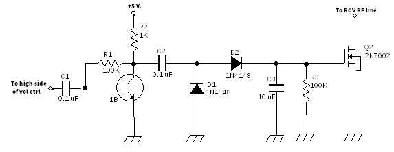
This simple project uses a single stage amplifier to tap into the audio at the input of the volume control, rectify it to a DC level, filter it, and use it to control a MOSFET as a shunt across the receive RF path. This project assumes that you have already installed the RF gain control described here (for the BITX40 or here (for the uBITX) and bridges across it at the control potentiometer.

R3 and C3 are used to not only filter out the audio component, but to form a “fast attack, slow release” control signal. That means that, when a strong signal appears, RF gain will be quickly reduced but will take a second or so to restore to full gain after the signal stops. This avoids “pumping” during a single sideband transmission but is fast to react to very loud signals.

Nearly any general purpose NPN bipolar junction transistor will work as Q1 as long as it has a beta of more than 100. 2N2222, 2N3904, etc. will work quite well. Q2 can be a 2N7000 or a BS170. None of the component values are critical. The 5 volt supply makes it easy to use any part with more than a working limit of just 6 volts and the current drain is low enough to be negligible.

I have found that most 2N7002 transistors will yield at least 20 dB of RF attenuation across the HF spectrum at 50 ohm impedance. Attenuation begins around 1.4 volt bias on the gate referenced to the source and provides maximum action at around the 3.7 volt level. Very effective for a single, simple, and inexpensive device. A great first step.

A more fulsome article with construction details (using surface mount components) is posted on nd6t.com.

This simple circuit led to a discussion on the BITX20 IO Group list, started by Jerry KE7ER, about the BAP64Q pin diode attenuator.   This gives 60dB of dynamic range:  https://groups.io/g/BITX20/message/32066

Attenuating back in RF gets around the limited dynamic range that Henning points out in the first post of that thread.    Note that the control voltage is inverted with respect to the 2n7002 FET, higher voltages give less attenuation.   You could get a slightly lower noise figure for the receiver if the attenuator was inserted at a later stage of the RF chain.

Jerry observes, “The BAP64Q is relatively expensive at $0.50 single piece,
the frugal among us will note it’s down at $0.20 if you buy a few thousand.
Mouser and Digikey both stock it, Mouser points you to the wrong BAP64* datasheet.   There are other similar small signal pin diode attenuators out there from other manufacturers.”

Reference

Mounting the display without screws showing on front panel

Mike WB8VGE claims, “mounting any LCD on a front panel is a pain”.  Probably most constructors would agree. Here’s how Mike does it without drilling holes in the corners to hold the display.

After you have painstakingly cut and filed the panel to allow the display to fit, fasten four .250 aluminum standoffs, one on each corner, and tighten with the correct screw. Use the shortest screw you have.
Check fitment and if necessary file away any panel material that might interfere with the display.
Using a sharpie pen, mark the corners. Don’t worry about being accurate, just a general location of each standoff will be enough.
Remove the display.
Use a bastard file and scratch around the area you just marked. The idea is to rough up the material.
Now, mix up a small batch of JB Weld.
Apply a generous amount to the bottom of each standoff, trying not to fill the hole up. (that’s why it’s best to use short screws so you don’t epoxy the screw in!)
Mount the display and with clamps, clamp the display onto the panel. I use small Irwin clamps and wood paint stirring sticks.
Wait 24 hours.
Whoa! You’ve mounted the display without trying to locate the mounting holes and without drilling holes!
Unless you go in there with a channel locks, you’re not going to be able to break the bond between the epoxy and the aluminum.

Tom  AB7WT has also tried this out.  He used shorter standoffs and put the JB weld on screws instead of longer standoffs. This way he could still unscrew the standoffs. It worked well and the screws were solid. The display and bezel look nice.

Reference

S-Meter on BITx40

Vic WA4THR has now added an S-Meter to his BITx40.  This uses the code supplied with the µBITx to show a meter, but which is not used in the firmware because there are no components to sense signal strength on the main board.

Reference

New release of KD8CEC firmware (v1.061)

Ian KD8CEC has released version 1.061  of his KD8CEC Firmware for the µBITx.  This adds the WSPR mode to your µBITx.   If  you use Ian’s uBITX Manager  to put WSPR information into uBITX (using your PC),  the µBITX no longer needs any external device to transmit WSPR.

Ian says, “Beta testers have been very helpful when embedding the WSPR functionality. WSPR mode will continue to improve in the future.

“By using WSPR before or after having a QSO, you can check where your uBITX is getting to around the world.”

Added or improved in version 1.061:

  1. 1.Added WSPR function to uBITX
  2. Update uBITX Manager to Version 1.0
  3. Reduced program size
  4. Fixed IF Shift Bug
  5. Other bugs fixed
  6. CWL, CWU mode are more friendly.  Two options are displayed for shifting frequency.

Please see the link below for details.
http://www.hamskey.com/2018/03/cat-support-ubitx-firmware-cec-version_24.html

You can download a HEX file (no need to use the Arduino IDE to load the firmware) and uBITX Manager from the link above.

You can also download the source code at https://github.com/phdlee/ubitx and see all the changes I’ve made so far.

LPF switching

Mike KU4QO suggests that how the relays select the relevant output low pass filter is done in a very clever way.

Control switching of LPFs

Three relays control four different filters.

  • When KT1, KT2 and KT3 are not energized, the 21-30MHz filter is selected.
  • With KT1 energized it bypasses the 21-30MHz filter and selects the 14-21MHz filter.
  • With KT1 and KT2 energized it bypasses both of those filters and selects the 7-10MHz filter.
  • With KT1, KT2 and KT3 energized it bypasses all filters except for the 3.5-5MHz filter.

The relays are only energized when transmitting (and only when needed).  It is an unusual configuration, saving the expense of a 4th relay.

Mike had a problem where he had no power out on 30m or 40m. Receive was fine. It ended up that one of the legs on relay KT2 was not soldered. A quick soldering of the pin and he was back in business.

Raj VU2ZAP responded, “Farhan has his mysterious ways of being thrifty. The real reason is as I think is to save one data out control line from Raduino.”

“The relays are known to fail, so I cut the TX line to filter ralays and linked it to +12V . The relays remain on during RX and  when you tune across bands you can hear them clicking! This affects power consumption but I can live with that.”

RF Path analysis

Jerry Gaffke KE7ER, provided an analysis of the RF path through the relays and suggested:

“With no relays energized as shown in the uBitx schematic,  RF power from the finals goes through KT1-14 to the 30m lowpass filter then through KT1-3 out to the antenna.   That’s as short as it can get.

“With KT1 energized and KT2 not, RF power goes through KT1-16 and KT2-14 to go through the 20m lowpass filter.  Still pretty short.

“With KT1 and KT2 both energized, we get the 40m lowpass filter through KT3-14.

“With KT1,KT2,KT3 all energized, we get the 80m lowpass filter through KT3-16.

“That’s getting to be a pretty long path for that RF, going through all three relays.  But at 3.5 – 4mhz it simply doesn’t matter.”

Reference