IK8YFW Giuseppe has used a cheap US$2 processor to create a DSP audio processing unit that works with any radio (including the µBITx).
The project was aimed at achieving an economic and simple DSP unit, based on the ARM Cortex STM32f103 processor module. Guiseppe implemented two narrow CW filters of about 300 and 700 hz and two SSB filters with a bandwidth of less than 2200 Hz and less than 3300 Hz. He also included a 6-level noise reduction algorithm. The project is a very cheap solution suitable for embedding in any and every QRP project. The project code can be found on Github. It is not perfect, as Guiseppe is still experimenting with the code. The project can be found here:
Ian KD8CEC’s test firmware supported extended extended buttons in Version 1.072 and this feature continues in the latest BETA release version 1.073.
Ian received from the beta testers to make the extended key (push button functions) a bit more flexible. He changed the feature to allow up to six pushbuttons (previously the maximum was four buttons) and functions that are allocated to buttons can now be selected by the user.
Description of changes
In uBITX Manager V1.04, up to 6 expansion keys (pushbutton keys) can be set as follows.
You need to set the role for the ‘Function’ item.
Function settings currently able to be controlled by buttons include:
0:None
1:Mode Select
2:Band Up
3:Band Down
4:Tune Step
5:VFO A/B Toggle
6:Split On/Off
7:TX On/Off
8:SDR Mode On/Off
9:RIT On/Off
In the above example, Button 1 is Mode Select, Button 2 is Band Up, Button 3 is Band Down, and Button 4 is Tune Step.
If you are a frequent CW practitioner, you can use the TX On / Off button as shown below:
Users may also want to turn off the transmit function by pressing button 4 during CW practice. At the end of the CW practice exercise, pressing button 4 would again activate the transmit function.
If you are a frequent user of SDR, you can probably set it up like this:
Since the Mode select function is not very important in SDR, a VFOA / VFO B toggle switch and SDR On / Off switch may be mapped instead.
As mentioned in the previous article, resistors can be any value (but keep them apart). Ian recommends you use resistor values over 100K (with values less than this reserved for later use cases).
Mike ZL1AXG found that resistor values greater than 500K were too close to the residual value sensed by the arduino analogue pin and caused the software to be unstable. Choose values between 100k and 500k.
There has been a bit of BITX20 IO Groups list chatter about the winner in ND6T’s AGC circuit (with RF gain control).
Ion VA3NOI has two versions of an ND6T AGC circuit board designed.
A through-hole single-side version measuring 17X38 mm.
An SMT board measuring 18X31 mm, with SMT components that are 0805 in size.
The . 1 uF cap is tantalum or niobium polarized.
The design was done using Eagle 7.5 freeware. The zip file in the Gerbers Folders should be uploaded to the PCB manufacturing house.
The boards are roughly 1 square inch in surface. You can place 10 boards on a 100X100 mm panel and get 10 panels for $5 plus shipping. For making into a kit, Ian recommends the SMT version as it will be more affordable and he expects it to have better performance on the upper bands.
He has ordered a through-hole version for experimenting with some values (AGC release time minimum resistor and coupling capacitors on RF line) and this is en route to Canada.
The PCBs have provision for adding a pot to adjust AGC release time and a switch to disable the AGC. Ion has posted the files (schematic, board layout and Gerbers) here:
Duwayne KV4QB has been playing with an Arduino Pro Mini and a small OLED display to use as a stand alone replacement for a analog meter. The existing Raduino in the µBITx does not have sufficinet spare analog input pins to provide everything that Duwayne wanted to measure.
John VK2ETA has produced a small piece of diagnostic firmware intended to be used by constructors to test out the Raduino.
The objective is to help original kit builders identify issues (e.g. wiring or “not working” problems), but also for more advanced experimenters both during construction and after “oops moments”.
So far it only tests the I2C bus, the communication with the SI5351 and the analogue inputs of the Raduino in a graphical form.
The plan is to expand to the audio circuit, the receiver chain, the TX low pass filters’ relays and hopefully more.
This is where be needs the input of other constructors to determine what to test for in the first instance and then some ideas to make the test results as simple but still useful to more advanced users.
John is looking for feedback as to what issues you had when building the kit that could potentially be incorporated in the diagnostic software. Tests need not be Arduino-only tests. Operator ‘s interpretation, as in “Do you hear the tone in the speaker, Y/N” are quite ok.
John has uploaded a beta version of the software to the IO Groups Files area:
Basic instructions are in the README.MD file in the top directory.
The main menu number 2 (Analogue inputs), brings a second level menu for testing the encoder inputs, the push button, the PTT, the Keyer and the spare analogue input.
Results are displayed in a horizontal bar graph with a scale from 0 to 5V representing the value read by the inputs. That way you can see how it matches the values your voltmeter indicates on the respective pin.
Results are shown only on changes to the values read, for example when rotating the encoder, pushing the PTT or the encoder push-button etc…
If no results are shown then your Arduino cannot read analogue inputs and it would mean plan-B: replacement of your Raduino.
Bruce KC1FSZ has been experimenting with a panadapter for his µBITx that is likely to be of interest to constructors, especially to anyone thinking about one of those fancy ICOM 7300s.
The goal was to build a crude panadapter into his BITX rig without resorting to external PCs, SDR dongles, etc. He used a few cheats in his scratch-build BITX that may make this a bit more tricky on a stock unit. However, Bruce is sure that someone in the group can figure out how to expand this into the mainstream.
It’s a bit like a Sweeperino. Bruce has built his firmware to quickly sweep the VFO across the band of interest (40m phone in Bruce’s case) and then to look at the AF spectrum at each point and display the result in a simplistic spectrum display. Obviously, this interrupts the receive for a brief instant when it is happening, but he has also set things up with an extra MOSFET so that the audio output can be suppressed during the sweep to hide the annoying sounds. This mod may already be in your rig if you’ve added an AGC.
The more sophisticated way to go is to do some DSP fiddling of the overlapping 3 kHz segments of the spectrum that are sampled during the sweep. At the moment Bruce sweeps in 500 Hz steps so there is overlap in the samples of the audio. This needs some more experimentation to get the optimal sweep speed, the cleanest way to stitch things together, averaging, etc. but even something basic is good enough to show the activity on the band.
Bruce also uses a cheap 128×64 OLED display, which makes these simple graphics possible. Be aware that these displays can be noisy.
The picture at the top of this news items shows what the initial display looks like. The caret at the very bottom is pointing to where the VFO is currently set. You know it’s working because you can always see the signature 7199 BITX birdie!
Bruce has produced a video with the sweep slowed and the audio on so you can hear how it works. It sounds like a strange SSTV mode, but it’s actually the entire 40m phone band being analyzed for activity.
Dennis KG4RUL has gone off the deep end with his µBITX. His current configuration, basically a rats nest on the bench, comprises:
Main CPU (Teensy 3.5) – handling the SI5351 control (I2C), the 20×4 LCD Display (I2c), input from the front panel controller (I2C), control of an AF DSP (I2C), control of a CW Keyer (I2C), monitoring of an SWR bridge, control of an RF Digital Attenuator (SPI)
Front Panel Controller (Pro-Mini) – interfaces with a rotary encoder w/switch and seventeen push buttons
AF DSP (Teensy 3.5) – implementing Low Pass, High Pass, Band Pass, Notch Filter and pass-through
In an earlier news item on ubitx.net, we speculated about projects under development by various teams. We speculated that Jack W8TEE was up to something that involved a touch screen display and a processor upgrade. Well the cat is now out of the bag. The photo below was post by Jack on the BITX20 list. This is the display panel of the JackAl board that the team will release shortly.
Al (AC8GY) and Jack picked the Teensy 3.6 because of its horsepower, good FFT library, and audio processing board. Al’s doing an info piece on JackAl which should answer most questions about it in an effort not to chew up the BITX20 group’s bandwidth.
There was no “target date” originally for announcement of the project. However, when Jack was asked to speak at FDIM, the project team thought it would be “kinda cool to show it off” at the Homebrew Show-and-tell on Friday night (8-10PM), so the target became real.
Al and Jack are starting to look like slugs who haven’t seen daylight in about six months. JackAl should be a fun board for a lot of people because its heart is the Teensy 3.6 which has lots of resources associated with it. Currently, we are using less than 10% of both flash and SRAM.
Jack says, “I hope to see a bunch of you at FDIM …”
KD8CEC Firmware Version 1.073 will be released within a day or two when testing is complete. You can download it right now and use it, but it may be further modified before final release.
Ian KD8CEC, in uBITX Firmware CEC Version 1.073 Beta, is supporting the use of up to 4 additional front-panel switches to control a range of functions normally only accessible via the menu system.
Preparations for adding additional function switches
Step 1: You will need four push switches and four resistors.
The value of the resistors is not particularly important, but a spread of resistance values is helpful. Ian recommends that the value of each resistance exceeds 100k ohms. This will allow the addition of more switches at a later date.
Ian uses 470k, 330k, 200k, and 150k in his example.
Step 2: Identify the wires on your function switch
Your rotary encoder will probably have a red wire and a yellow wire currently connected to the switch (not the three way connector on the encoder, but the two way connector). These wires connect to Pin 4 and Pin 5 of the raduino connector respectively.
When you press the function switch on the rotary encoder the red wire (which connects to an analogue input on the arduino nano) becomes grounded to the yellow wire.
3. Install your switches and connect up resistors in series with the switches
Install up to four switches with connections paralleled with the encoder switch. One side of each switch should be connected to the red wire on the encoder switch. The other side of each switch should be connected to a resistor that is in turn connected to the yellow wire on the encoder as illustrated in the photo below.
All resistors should be of a different value. A good starting point would be the values that Ian used, but if you don’t have these in the junk box, choose values you do have – as separated in value as possible.
4.Setting the switch values in the KD8CEC firmware.
You now need to save the switch information in Ian’s uBITX firmware. To do this you need to have installed and run the KD8CEC uBITX Manager software. This runs on virtually any version of Windows, and on Linux. See Ian’s website for further details. and to download the current version of uBITx manager.
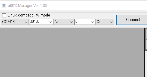
Extended switch settings are supported in uBITX Manager Version 1.03 or later. Go through the following steps:
A) Connect -> Read
B) ‘Decode =>’ -> Scroll down
You will see a screen that manages the ‘Extended Key’ as shown below.
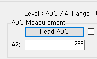
C) Press the Read ADC button.
It will probably have a value of around 254. This is the Analogue to Digital conversion value being read by the Arduino Nano on Analogue Pin A6 to which the function key is connected and then divided by 4.
The reason for dividing by 4 is to reduce the number of bytes required for storage of the value in EEPROM. Accuracy of the analogue read means that greater precision is unnecessary.
Setting the mode button value
You should now measure the value when you press a button. Click ‘Read ADC’ while holding the switch you have chosen to be used as ‘Select Mode’.
Try one or two more times and average your results.
Enter the measured value into the ‘Mode’ value on the left.
Ian connected a 470k resistor to the ‘Select Mode’ switch, so the ADC result was 235. He set the range to -1 to +1 to prevent the switch from malfunctioning.
The values vary depending on the resistance you have used, the state of the switch, and the length of the cable.
Enter values for Band Up, Band down and Tune Step functions
In this way, enter values for the ‘Band Up’, ‘Band Down’ and ‘Tune Step’ switches
At the end of this process you should have something like this in the table in uBITx Manager:
If the switch is not installed (i.e. it is free floating while you try out this concept) it may be difficult to click on the ‘Read ADC’ at the same time as holding down the switch. In this case, select ‘5 Sec Delay’ and click the ‘Read ADC’ button to see the count down:
When you have finished setting up the ADC ranges for each switch, you should select “encode” and then write the data to the µBITx. Reboot your µBITx and you should now have four new switches on your front panel to avoid having to delve into the menu system to control everything on your rig.
Below is the link to a video that Ian has provided to help illustrate how to wire up the switches and set the ADC values in uBITx Manager.
After pointing out an out-of-date reference on uBITx.net to wire up diagram faults on the HF Signals website, Patrick W7PEA has set out to develop the Wiki (already on the BITX20 IO GROUP website), starting with a more fully developed Wire Up and Assembly Guide.
Because this is a Wiki anybody can contribute to the effort.
This immediately revealed a PDF developed by Bob W4RJP. This began as a simple wiring diagram to assist in wiring up the uBitX and was never intended for publication. While Bob’s µBitX is still mostly stock, over time I did revise the diagram to include a few options as well as beneficial corrective actions identified by other builders.

 IK8YFW Giuseppe has used a cheap US$2 processor to create a DSP audio processing unit that works with any radio (including the µBITx).
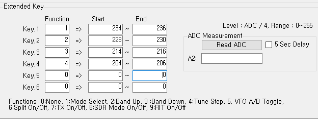


 In an earlier news item on ubitx.net, we speculated about projects under development by various teams. We speculated that Jack W8TEE was up to something that involved a touch screen display and a processor upgrade. Well the cat is now out of the bag. The photo below was post by Jack on the BITX20 list. This is the display panel of the JackAl board that the team will release shortly.