
KD8CEC Firmware Version 1.073 will be released within a day or two when testing is complete. You can download it right now and use it, but it may be further modified before final release.

Ian KD8CEC, in uBITX Firmware CEC Version 1.073 Beta, is supporting the use of up to 4 additional front-panel switches to control a range of functions normally only accessible via the menu system.
Preparations for adding additional function switches
Step 1: You will need four push switches and four resistors.
The value of the resistors is not particularly important, but a spread of resistance values is helpful. Ian recommends that the value of each resistance exceeds 100k ohms. This will allow the addition of more switches at a later date.
Ian uses 470k, 330k, 200k, and 150k in his example.

Step 2: Identify the wires on your function switch
Your rotary encoder will probably have a red wire and a yellow wire currently connected to the switch (not the three way connector on the encoder, but the two way connector). These wires connect to Pin 4 and Pin 5 of the raduino connector respectively.

When you press the function switch on the rotary encoder the red wire (which connects to an analogue input on the arduino nano) becomes grounded to the yellow wire.
3. Install your switches and connect up resistors in series with the switches
Install up to four switches with connections paralleled with the encoder switch. One side of each switch should be connected to the red wire on the encoder switch. The other side of each switch should be connected to a resistor that is in turn connected to the yellow wire on the encoder as illustrated in the photo below.
All resistors should be of a different value. A good starting point would be the values that Ian used, but if you don’t have these in the junk box, choose values you do have – as separated in value as possible.

4.Setting the switch values in the KD8CEC firmware.
You now need to save the switch information in Ian’s uBITX firmware. To do this you need to have installed and run the KD8CEC uBITX Manager software. This runs on virtually any version of Windows, and on Linux. See Ian’s website for further details. and to download the current version of uBITx manager.
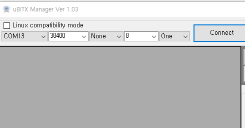
Extended switch settings are supported in uBITX Manager Version 1.03 or later. Go through the following steps:
A) Connect -> Read

B) ‘Decode =>’ -> Scroll down
You will see a screen that manages the ‘Extended Key’ as shown below. 
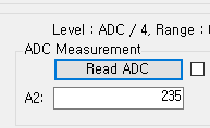
C) Press the Read ADC button.

It will probably have a value of around 254. This is the Analogue to Digital conversion value being read by the Arduino Nano on Analogue Pin A6 to which the function key is connected and then divided by 4.
The reason for dividing by 4 is to reduce the number of bytes required for storage of the value in EEPROM. Accuracy of the analogue read means that greater precision is unnecessary.
Setting the mode button value
You should now measure the value when you press a button. Click ‘Read ADC’ while holding the switch you have chosen to be used as ‘Select Mode’.
Try one or two more times and average your results.
Enter the measured value into the ‘Mode’ value on the left.

Ian connected a 470k resistor to the ‘Select Mode’ switch, so the ADC result was 235. He set the range to -1 to +1 to prevent the switch from malfunctioning.
The values vary depending on the resistance you have used, the state of the switch, and the length of the cable.
Enter values for Band Up, Band down and Tune Step functions
In this way, enter values for the ‘Band Up’, ‘Band Down’ and ‘Tune Step’ switches
At the end of this process you should have something like this in the table in uBITx Manager:

If the switch is not installed (i.e. it is free floating while you try out this concept) it may be difficult to click on the ‘Read ADC’ at the same time as holding down the switch. In this case, select ‘5 Sec Delay’ and click the ‘Read ADC’ button to see the count down:

When you have finished setting up the ADC ranges for each switch, you should select “encode” and then write the data to the µBITx. Reboot your µBITx and you should now have four new switches on your front panel to avoid having to delve into the menu system to control everything on your rig.
Below is the link to a video that Ian has provided to help illustrate how to wire up the switches and set the ADC values in uBITx Manager.
In the video version marked (final), the interface shows 6 possible switches which you can set up. This article mentions 4 switches. I’m wondering if I can just add another appropriately sized switch+resistor to make 5 switches? Suggestions on resistor sizes? THanks
-Jonathan
Jonathan
The video was made by Ian at an earlier date. In the updated final version the firmware will acommodate up to 6 switches and a wider range of functions can be selected by the user to assign to switches.
Mike ZL1AXG ubitx.net