The KD8CEC firmware provides a lot of customisation features through uBITx Manager software. Many user of Ian’s firmware are not aware of all the built-in features of his firmware. This is one such instance!
JJ1EPE raised a concern that his display in CW mode was “off frequency”. Well, it was from his perspective, but then the display was all the time showing the TX frequency not the offset frequency where the station he was listening to.
CW offsets create headaches in how you represent the frequency on a display. In SSB the frequency you see on the display is the frequency of the suppressed carrier on receive and the same on transmit. If you tune to the carrier frequency of a received station you won’t hear anything. To get a sidetone we have to tune off the transmit frequency by a few hundred hertz. Most people have worked out how to set the offset on the uBITx.
The standard that Ian KD8CEC has applied is to always show the TX frequency by default (except where RIT or SPLIT mode is selected).
However, if you want to change the approach, do the following in uBITX Manager:
– Enable Adjust CW Frequency
– Shift Display Frequency on CWL, CWU Mode
If you select this function, the LCD will show the frequency at which the radio is being transmitted (the offset you prefer is added or subtracted to the actual RX frequency reflecting the CW-L or CW-U mode selected). This may be just the thing you were looking for!
Michael VE3WMB figured after playing around with the KD8CEC firmware for a while that he would prefer to have the Main VFO frequency and Mode displayed in the top line, instead of the bottom line of the display and the secondary info (VFO B etc) on the bottom line of his display.
Under ‘User Interface’ of the uBitx Memory Manager application (scroll way down), checking the ‘1/2 Line Toggle’ works to swap the first and 2nd lines on the display. No coding is required to achieve this.
Ian KD8CEC has formally released version 1.08 of his firmware. This the first major release since 1.061, although there have been a number of Beta versions in between that many constructors will have donwloaded.
Some key features in this version include:
1.Receive performance is improved compared to the original firmware or version 1.061
2.ATT function has been added to reduce RF gain (This shifts the 45Mhz IF passband down the slope of the filter giving an attenuator effect).
3.Added the ability to connect an inboard or outboard SDR unit after the 45MHz roofing filter (A low cost RTL-SDR is available that can be controlled by computer software providing a full SDR receiver)
4.Added ADC Monitoring in CAT communications
5. Supports several LCD variants including:
16×02 Parallel LCD – i.e. LCD equipped with µBITX
the 16×02 LCD display configured to use I2C
20×04 Parallel LCD with existing wiring in the µBITx
20×04 LCD display configured to use I2C
Two 16×02 LCD displays configured to use I2C (Dual LCD mode)
6.Added extended switch support (up to 6 switches can be incorporated on your front panel to control various rig functions).
7. S Meter support – Any S-meter should be compatible. The S-Meter will work on 2 or 4 line displays.
8.Added S-Meter Setting Assistant to uBITX Manager
You can download HEX file and uBITX Manager from the link above. You can also download the source code at https://github.com/phdlee/ubitx and see all the changes I’ve made so far. If there is a non-critical bug in the public version, Ian will link to the new firmware from his blog.
A new version of the CEC firmware manual is anticipated shortly.
Ashhar invites you all to test it. if you are not familiar with C code or Arduino programming, it is suggested you wait for a few days until we get all the bugs sorted out. This is only for Arduino regulars.
Send any bug reports directly to Ashhar’s email box at farhanbox@gmail.com. In the subject line use the word “#ubitx40”. I will try to answer all emails but I can’t promise responses to all.
Ashhar has measured the mood of the BITX20 list and has made the call to substantially borrow from Ian KD8CEC’s code and back port it to the original ubitx code. The new code has about 10% more lines but it is substantially more robust and useful.
The main features that Ashhar has cherry picked from Ian’s code are:
1. Keyer. You have to choose which keyer type to use, but the keying is much better and robust now. This code is a total copy/paste of Ian’s keyer. The auto-keyer (that sends out preset phrases in CW) is left out. The Iamabic A, Iambic B and the handkey sending works very well.
2. CAT control. Given the popularity of FT8, Ashhar has rewritten the CAT control by following Ian’s code but follows the ubitx coding conventions. It represents a miminal set of controls.
3. Split operation has been included.
4. Rationalised menus: the menu system is now more consistent.
5. Tuning mechanism: The accelerated tuning works, and it doesn’t jump randomly like before, nor does it work at the same speed. For very long band changes, it is recommended to use the menu option to change band.
Among the things left out was support for different types of displays, WSPR, and many other goodies. The EEPROM memory map has been kept consistent with KD8CEC’s plan. You can switch between both code bases easily.
Ashhar has kept usage of English words at a minimum.
“Given that Dr.Lee’s software is now pretty stable from 1.06 onwards, what do you all say about using this as the ‘shipped’ firmware?”
The responses have been varied.
The case for using KD8CEC firmware
uBITx.net has supported the suggestion of supplying the KD8CEC version as the default firmware. There is no question that the KD8CEC sketch represents more mature firmware. It runs on an unmodified uBITx, but provides for minor hardware enhancements that add additional functionality. All other firmware options require hardware changes prior to installation, so there is no obvious contender from other firmware developers at this juncture. This is not to downgrade the importance and innovation brought by other firmware developers. Each firmware hack has its merits and brings features that are important to groups of µBITx constructors. No other firmware, other than the stock firmware, has such a large group of supporters.
The KD8CEC software brings a significant increase in the range of features and reliability of the product. Manuals are available for both the stable version and the beta version of the firmware. The factory product does not come with a manual, has not been improved in six months or even had basic bugs removed, and has caused frustration for some constructors. This is not to say, that the stock firmware is of low quality – it is basically sound, but needs work. Ashhar has not had time to address these issues because of the huge demand for the µBITx and need to resolve other issues as they have arisen.
The case for not using KD8CEC firmware
There are of course arguments against using the KD8CEC version as the factory install. The feature packed nature of the firmware leaves little room for constructors to hack the firmware to customise it for their own purposes. This has been largely overcome now through the modularity of the latest firmware design. Features can be enabled or disabled in the configuration section of the code. This modularity will become increasingly important as hardware enhancements are combined with code to support the hardware changes. The addition of uBITx Manager software for the PC expands the potential to customise the firmware in future to reflect different hardware configurations.
Suggestions that the firmware is not a good fit, because the factory alignment procedure is not included by default, is a complete red herring. Different features can be configured by setting a few configuration flags in the sketch. This is a configuration issue, not a practical issue. The code remains in the sketch and the sketch can be simplified by removing many of the extensions through a simple five minute configuration exercise to produce a stock version.
Some prefer Ashhar Farhan’s unique approach to tuning. This is a matter of personal preference. Again, this feature could be reincorporated easily, and enabled or disabled through a single configuration setting that chooses the tuning style that suits the user.
The biggest improvements to functionality for just about any modern appliance come as a result of firmware enhancements. µBITx firmware enhancements come free, but hardware enhancements cost constructors.
Note: This article reflects the personal views of the author (Mike ZL1AXG) and not those of the manufacturer.
SP VU2SPF and Joe VE1BWV have just released the latest version of the TFT Colour Touch Control software.
Highlights
This software/hardware combination is low cost, uses standard easy to get parts and provides a colour, touch control and physical buttons if you want them.
You will require a TFT (Touch) Display module, an At Mega 2650 arduino board, Si5351 DDS module, a µBITx and a few wires
The result is an all-band rig with a computer controlled Radio Touch Control Colour Display.
Some new features
Automatic Scanning – up to band edges in both the directions is now added in V2.9bU of software. Scanning finds signals of interest across the band. Two small buttons labeled ‘U’ and ‘D’ scan in up and down from the currently set frequency. Scanning can be stopped by touching the display panel.
CAT Control – the software now has new code to emulate FT817 CAT commands. This provides radio and computer control for digital modes.
User Manual– A new comprehensive user manual has also been added. Constructors have been looking for this for quite a while.
Ian KD8CEC’s test firmware supported extended extended buttons in Version 1.072 and this feature continues in the latest BETA release version 1.073.
Ian received from the beta testers to make the extended key (push button functions) a bit more flexible. He changed the feature to allow up to six pushbuttons (previously the maximum was four buttons) and functions that are allocated to buttons can now be selected by the user.
Description of changes
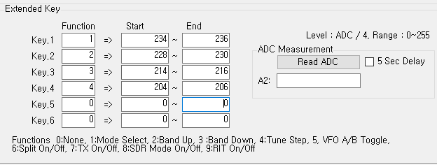
In uBITX Manager V1.04, up to 6 expansion keys (pushbutton keys) can be set as follows.
You need to set the role for the ‘Function’ item.
Function settings currently able to be controlled by buttons include:
0:None
1:Mode Select
2:Band Up
3:Band Down
4:Tune Step
5:VFO A/B Toggle
6:Split On/Off
7:TX On/Off
8:SDR Mode On/Off
9:RIT On/Off
In the above example, Button 1 is Mode Select, Button 2 is Band Up, Button 3 is Band Down, and Button 4 is Tune Step.
If you are a frequent CW practitioner, you can use the TX On / Off button as shown below:
Users may also want to turn off the transmit function by pressing button 4 during CW practice. At the end of the CW practice exercise, pressing button 4 would again activate the transmit function.
If you are a frequent user of SDR, you can probably set it up like this:
Since the Mode select function is not very important in SDR, a VFOA / VFO B toggle switch and SDR On / Off switch may be mapped instead.
As mentioned in the previous article, resistors can be any value (but keep them apart). Ian recommends you use resistor values over 100K (with values less than this reserved for later use cases).
Mike ZL1AXG found that resistor values greater than 500K were too close to the residual value sensed by the arduino analogue pin and caused the software to be unstable. Choose values between 100k and 500k.
KD8CEC Firmware Version 1.073 will be released within a day or two when testing is complete. You can download it right now and use it, but it may be further modified before final release.
Ian KD8CEC, in uBITX Firmware CEC Version 1.073 Beta, is supporting the use of up to 4 additional front-panel switches to control a range of functions normally only accessible via the menu system.
Preparations for adding additional function switches
Step 1: You will need four push switches and four resistors.
The value of the resistors is not particularly important, but a spread of resistance values is helpful. Ian recommends that the value of each resistance exceeds 100k ohms. This will allow the addition of more switches at a later date.
Ian uses 470k, 330k, 200k, and 150k in his example.
Step 2: Identify the wires on your function switch
Your rotary encoder will probably have a red wire and a yellow wire currently connected to the switch (not the three way connector on the encoder, but the two way connector). These wires connect to Pin 4 and Pin 5 of the raduino connector respectively.
When you press the function switch on the rotary encoder the red wire (which connects to an analogue input on the arduino nano) becomes grounded to the yellow wire.
3. Install your switches and connect up resistors in series with the switches
Install up to four switches with connections paralleled with the encoder switch. One side of each switch should be connected to the red wire on the encoder switch. The other side of each switch should be connected to a resistor that is in turn connected to the yellow wire on the encoder as illustrated in the photo below.
All resistors should be of a different value. A good starting point would be the values that Ian used, but if you don’t have these in the junk box, choose values you do have – as separated in value as possible.
4.Setting the switch values in the KD8CEC firmware.
You now need to save the switch information in Ian’s uBITX firmware. To do this you need to have installed and run the KD8CEC uBITX Manager software. This runs on virtually any version of Windows, and on Linux. See Ian’s website for further details. and to download the current version of uBITx manager.
Extended switch settings are supported in uBITX Manager Version 1.03 or later. Go through the following steps:
A) Connect -> Read
B) ‘Decode =>’ -> Scroll down
You will see a screen that manages the ‘Extended Key’ as shown below.
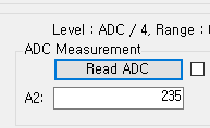
C) Press the Read ADC button.
It will probably have a value of around 254. This is the Analogue to Digital conversion value being read by the Arduino Nano on Analogue Pin A6 to which the function key is connected and then divided by 4.
The reason for dividing by 4 is to reduce the number of bytes required for storage of the value in EEPROM. Accuracy of the analogue read means that greater precision is unnecessary.
Setting the mode button value
You should now measure the value when you press a button. Click ‘Read ADC’ while holding the switch you have chosen to be used as ‘Select Mode’.
Try one or two more times and average your results.
Enter the measured value into the ‘Mode’ value on the left.
Ian connected a 470k resistor to the ‘Select Mode’ switch, so the ADC result was 235. He set the range to -1 to +1 to prevent the switch from malfunctioning.
The values vary depending on the resistance you have used, the state of the switch, and the length of the cable.
Enter values for Band Up, Band down and Tune Step functions
In this way, enter values for the ‘Band Up’, ‘Band Down’ and ‘Tune Step’ switches
At the end of this process you should have something like this in the table in uBITx Manager:
If the switch is not installed (i.e. it is free floating while you try out this concept) it may be difficult to click on the ‘Read ADC’ at the same time as holding down the switch. In this case, select ‘5 Sec Delay’ and click the ‘Read ADC’ button to see the count down:
When you have finished setting up the ADC ranges for each switch, you should select “encode” and then write the data to the µBITx. Reboot your µBITx and you should now have four new switches on your front panel to avoid having to delve into the menu system to control everything on your rig.
Below is the link to a video that Ian has provided to help illustrate how to wire up the switches and set the ADC values in uBITx Manager.