
Ashhar Farhan VU2ESE reports today that he has had coffee with Ehsan from HF Signals and can confirm that they will be shipping µBITx ordered 6 May tomorrow. The backlog appears to have been bet!
K5BCQ boards very popular
 The list of potential orders for Keys K5BCQ on 3 May is surprisingly high (250+). Email Keys K5BCQ(at)ARRL.net (to keep from overloading this “topic”) and he’ll update the spreadsheet to include or amend your order.
Reference
VA7AT Audio Pop and ND6T AGC Fixes: PCBs
Would you would like to have fixes in your µBITx for the audio pop and the missing AGC issues?
There are now two proven designs to the audio pop and AGC issues from:
- VA7AT for the audio pop problem
- ND6T for an effective AGC
Kees K5BCQ is taking orders now for two small PCBs to make it easier for constructors to complete these fixes. The PCBs require the use of surface mount components. They are tiny (about 1″ square) and can easily be mounted in any case. They will be very cheap and available both in the US and DX.
Reference
uBITx panels for EF01 Excellway case

Bought the Banggood case? Want some 3D printed drop in front and back panels so you don’t need to cut out the hole for the display and controls?
Gary AG5TX says:
“I bet some find it hard to stomach buying $27 plastic panels for a $10 plastic case when debating a few bucks differences in micro-controllers.
That said, my building brother, I too get anxious on cutting holes. We don’t know what tools you have, and given the question, assume not a mill or a drill press.
“What I would do is cover the front side of the plastic panel with blue 3M painters tape. Scribe the centerline for the holes directly on the ‘inside the box’ portion of the plastic where it won’t be seen. I use center drills to start the holes (they are cheap), if you don’t have center drills, use a small drill bit. Once the initial undersized holes are cut, flip the piece over and drill from the ‘outside the box’ side so if you get a chip out it won’t be seen. Best to start small and step up to one drill bit less than size. When drilling, secure the plastic panel over a scrap piece of softwood, and make this a “pine board project.” With thin plastic and drilling with hand tools, I find that the final drill bit size is best done by hand. I have an old pcb hand nibbler tool ($10?) for cutting somewhat square holes with patience. Just slightly undercut the rectangle for the LCD with the nibbler, remove the tape and finish out with a bastard file and sand paper. If all goes wrong, you can still try 2 more cases or spend the $27. Also search this forum for good ideas on printing a full face ‘label’ which might cover up the sins of a nonperfect cut. Stain grade or paint grade? My wood working Grandfather taught me very early in life that a coat of paint covers a multitude of sins. Nothing ventured, nothing learned. Maybe someone else has some tips.”
Michael VE3WMB comments:
“I have now used three of the Excelway EF01 cases for rigs with 16 X 2 displays with good success. The ABS enclosure panels are quite easy to work with.
“Just to add a couple of comments to Gary’s suggestions. I have found that drilling corner holes and using a coping saw to cut out the “window” for the display works quite well. As Gary suggests you want to make it undersized by a couple of millimetres. With patience and a nibbler or even an exacto knife and a file you can make a decent looking opening. In all three cases I made
the “window” just large enough to friction fit the display without resorting to using screws to hold it in place and this works fine.
“One other point; I suggest that you mark the position of where you are going to drill holes and then make a small divot (a nail and hammer works fine for this) so that the drill doesn’t wander. Also starting with a small sized drill bit first helps. For larger holes (i.e. for BNC etc) I swear by a stepped drill bit to get the hole to the proper size.
“The key to getting a good result is to plan and carefully mark everything in advance on the back of the panels and then take your time. Remember if an opening is too small you can enlarge it, if it is too big there is not a lot you can do so, measure twice and cut once.”
MVS Sarma says, “For cutting rectangular windows in plastic, I resort to a lamination cutter sold in India at just fraction of a $. I keep the tool drawing across the 4 lines of the rectangle (the lcd mounting window in this case on the µBITx). After a while you can push out the small window from the plastic.
This is what a laminate cutter looks like.
Reference
uBITx at FDIM and Dayton Hamvention?

W8TEE will be talking about his µBITx at QRP Club Night at FDIM (Friday 17 May. Hans G0UPL from QRP Labs has a table at the vendor evening at FDIM (Thursday 17-May-2018). It is understood that the µBITx designer from HFSignals.com (Ashhar Farhan) will also be at FDIM.
Hans G0UPL also has a booth at the Dayton Hamvention, #6414. He plans to have a good selection of QRP Labs kits on show and for sale.
There will undoubtedly be a number of µBITx constructors at Hamvention. Any suggestions for a hang-out spot to share your µBITx tips?
Reference
Photo of mod for evening up power output
Nigel G4ZAL did Howard WB2VXW ‘s mod by adding:
- 27uH inductor in series with R86 (NB calculated value)
- Adding parallel caps of 220pF on top of R87 and R88.
The mods to the main board are shown in the photo below.

The power output changes that resulted were as follows:
- 7MHz from 12.5w to 14.5w
- 14MHz from 7w to 11.5w
- 21MHz from 4w to 8w
- 28MHz from 2w to 4w
Nigel says it is a “very worthwhile mod for just 3 components”. This mod is something that all constructors should consider.
Reference
How will you know you need to calibrate your BFO?
- Tune to 7074 using LSB. You should hear nothing.
- Change to USB and you should hear all kinds of PSK and other digital modes. If you hear these signals in LSB then your BFO frequency is not correct, and may even be placed on the wrong side of the passband.
My BFO was way off after I first tried to calibrate it. I then started over with mine at 996.4 and ended up at 996.7. If yours is a long way off from that then I’ll bet you hear psk at 7074 when in LSB.
Reference
KD8CEC firmware now supports 6 switches
Ian KD8CEC’s test firmware supported extended extended buttons in Version 1.072 and this feature continues in the latest BETA release version 1.073.
Ian received from the beta testers to make the extended key (push button functions) a bit more flexible. He changed the feature to allow up to six pushbuttons (previously the maximum was four buttons) and functions that are allocated to buttons can now be selected by the user.
Description of changes
In uBITX Manager V1.04, up to 6 expansion keys (pushbutton keys) can be set as follows.
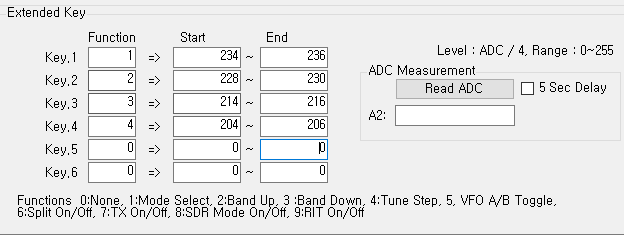
You need to set the role for the ‘Function’ item.

Function settings currently able to be controlled by buttons include:
0:None
1:Mode Select
2:Band Up
3:Band Down
4:Tune Step
5:VFO A/B Toggle
6:Split On/Off
7:TX On/Off
8:SDR Mode On/Off
9:RIT On/Off
In the above example, Button 1 is Mode Select, Button 2 is Band Up, Button 3 is Band Down, and Button 4 is Tune Step.
If you are a frequent CW practitioner, you can use the TX On / Off button as shown below:

Users may also want to turn off the transmit function by pressing button 4 during CW practice. At the end of the CW practice exercise, pressing button 4 would again activate the transmit function.
If you are a frequent user of SDR, you can probably set it up like this:

Since the Mode select function is not very important in SDR, a VFOA / VFO B toggle switch and SDR On / Off switch may be mapped instead.
As mentioned in the previous article, resistors can be any value (but keep them apart). Ian recommends you use resistor values over 100K (with values less than this reserved for later use cases).
Mike ZL1AXG found that resistor values greater than 500K were too close to the residual value sensed by the arduino analogue pin and caused the software to be unstable. Choose values between 100k and 500k.
Simulated S-Meter and SWR meter on small OLED display


Duwayne KV4QB has been playing with an Arduino Pro Mini and a small OLED display to use as a stand alone replacement for a analog meter. The existing Raduino in the µBITx does not have sufficinet spare analog input pins to provide everything that Duwayne wanted to measure.
More information can be found on his blog at:
https://kv4qb.blogspot.com/2018/04/stand-alone-simulated-analog-meter.html
He is also working on a small board to provide forward and reflected power readings for SWR metering and power measurement.
This has created a bit of interest on the list, and represents an interesting idea that is potentially adaptable to other projects and use cases.
Reference
Arduino Nano test analogue inputs

John VK2ETA has produced a small piece of diagnostic firmware intended to be used by constructors to test out the Raduino.
The objective is to help original kit builders identify issues (e.g. wiring or “not working” problems), but also for more advanced experimenters both during construction and after “oops moments”.
So far it only tests the I2C bus, the communication with the SI5351 and the analogue inputs of the Raduino in a graphical form.
The plan is to expand to the audio circuit, the receiver chain, the TX low pass filters’ relays and hopefully more.
This is where be needs the input of other constructors to determine what to test for in the first instance and then some ideas to make the test results as simple but still useful to more advanced users.
John is looking for feedback as to what issues you had when building the kit that could potentially be incorporated in the diagnostic software. Tests need not be Arduino-only tests. Operator ‘s interpretation, as in “Do you hear the tone in the speaker, Y/N” are quite ok.
John has uploaded a beta version of the software to the IO Groups Files area:
Basic instructions are in the README.MD file in the top directory.
The main menu number 2 (Analogue inputs), brings a second level menu for testing the encoder inputs, the push button, the PTT, the Keyer and the spare analogue input.
Results are displayed in a horizontal bar graph with a scale from 0 to 5V representing the value read by the inputs. That way you can see how it matches the values your voltmeter indicates on the respective pin.
Results are shown only on changes to the values read, for example when rotating the encoder, pushing the PTT or the encoder push-button etc…
If no results are shown then your Arduino cannot read analogue inputs and it would mean plan-B: replacement of your Raduino.