New AGC system

Don ND6T has been tinkering with AGC mods, and has come up with a new solution that gives much high levels of RF compression.

The µBITX presents some challenges with RF AGC system design: There is no RF preamplifier to use as a voltage-controlled attenuator, it is broadband and includes no tuned circuits in the receive path, and the intermediate frequency amplifiers are not configured for variable gain.

If we try to use a PIN diode in the RF, the high insertion loss raises the receiver over-all noise figure appreciably and the driver circuitry begins to become complex. The diode array also necessitates a fair additional current drain.

Original solution

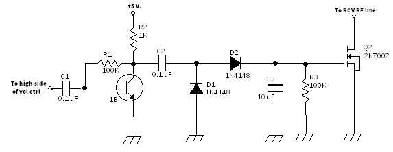
Don’s original solution, designed for the BITX40, was to use a 2N7002 MOSFET as a shunt from RF to ground. The advantages were the simple circuit, the low current drain, and no insertion loss. The disadvantage was the limited dynamic control range (about 20 dB ). This was primarily due to the finite series resistance of the MOSFET when it was driven to full conduction, about 5 ohms. You can see this project by clicking here.

Putting another FET in series

Numerous experiments revealed that adding another 2N7002 in series with the receive RF path made it possible to add another 20 dB (or so) dynamic range across the HF spectrum. This was controlled with the same control bias as the original but the configuration requires driving the source connection of the transistor with the control and biasing the gate at 2.5 volts so that, at idle, the series transistor is driven to full conduction. This control topography requires that the new series transistor to be DC blocked from the RF line.

Pre-requisite Mod

This project assumes that you have already installed the manual RF Gain Control modification since it requires that the trace between relay K1 and relay K3 be cut. I designed mine to simply be glued on the back of the control potentiometer and cut the single-sided un-etched printed circuit board stock to be about 20 mm by 13 mm. The thickness of the completed circuit is only 3 mm and so fits easily.

Theory

Detected audio from the receive audio pre-amplifier is sampled by bringing a twisted pair of wires from the volume control. Just attach the pair across the outside terminals of the control, attaching the wire from the “hot” terminal (which also attaches to “audio1” plug on the main board, pin 4) to the vacant side of C1 on the new board. The other wire attached to the “cold” terminal (which also attaches to pin 3 of the “audio1 plug) connects the the “GND” area of the new board.

This audio sample is then amplified by Q1 and fed through C2 to be rectified by diodes D1 and D2 and filtered by C4 to become the AGC control bias. Signals below 30 millivolts RMS leaves the circuit idle, with Q2 (the series element) biased to full conduction and only adds about 0.6 dB of loss. Q3 (the shunt element) is biased to cutoff and has no effect on the receive signal. Louder signals (S9 and above) create higher bias voltages until maximum is reached (about 1 volt RMS audio) at about 3 volts DC control bias. At this point attenuation is about 50 dB at 3.5 MHz, 34 dB at 30 MHz.

The time constant of C4 and R6 sets the “AGC release” rate, several seconds from full to idle. Charging time is fast, milliseconds, so that sudden strong signals are handled without discomfort. This ratio prevents oscillation and diminishes “pumping” on strong signals. For faster recovery rates, decrease the resistance value of R6. Values down to 100 K work satisfactorily but 1 megaohm worked the best for me.

Construction

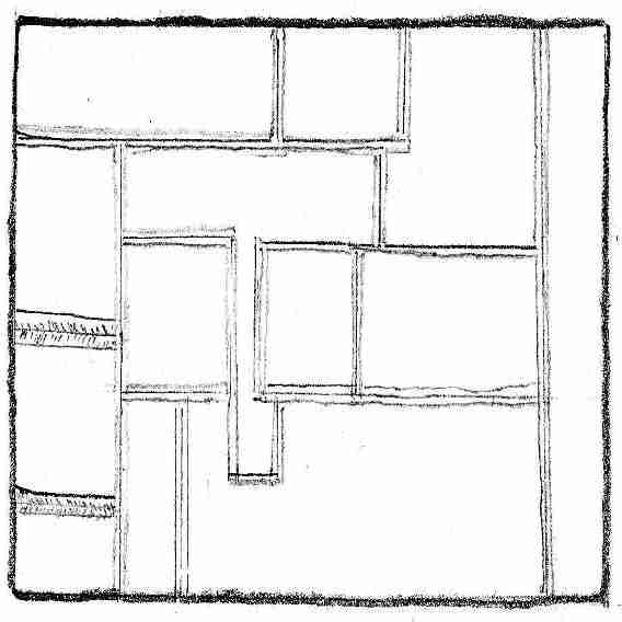
A hobby knife was used to isolate the connection pads as shown in the sketches. The remaining copper is then lightly tinned. Resistance checks should then be made to insure that there are no copper scraps or solder bridges between the lands.

I often find it convenient to simply begin in the top right corner of a board and work my way down and left so that I avoid working over previously completed circuit areas. Just place a component, hold it down, and touch the soldering iron to the board near one of the component leads. The thin solder will make a weak attachment to the component (called “tacking”). The builder can then move to another connection on that part and properly solder it using a hand to hold the solder. Then the rest of the component is soldered properly and the value checked with metering to assure a good connection and that the part wasn’t damaged in the process.


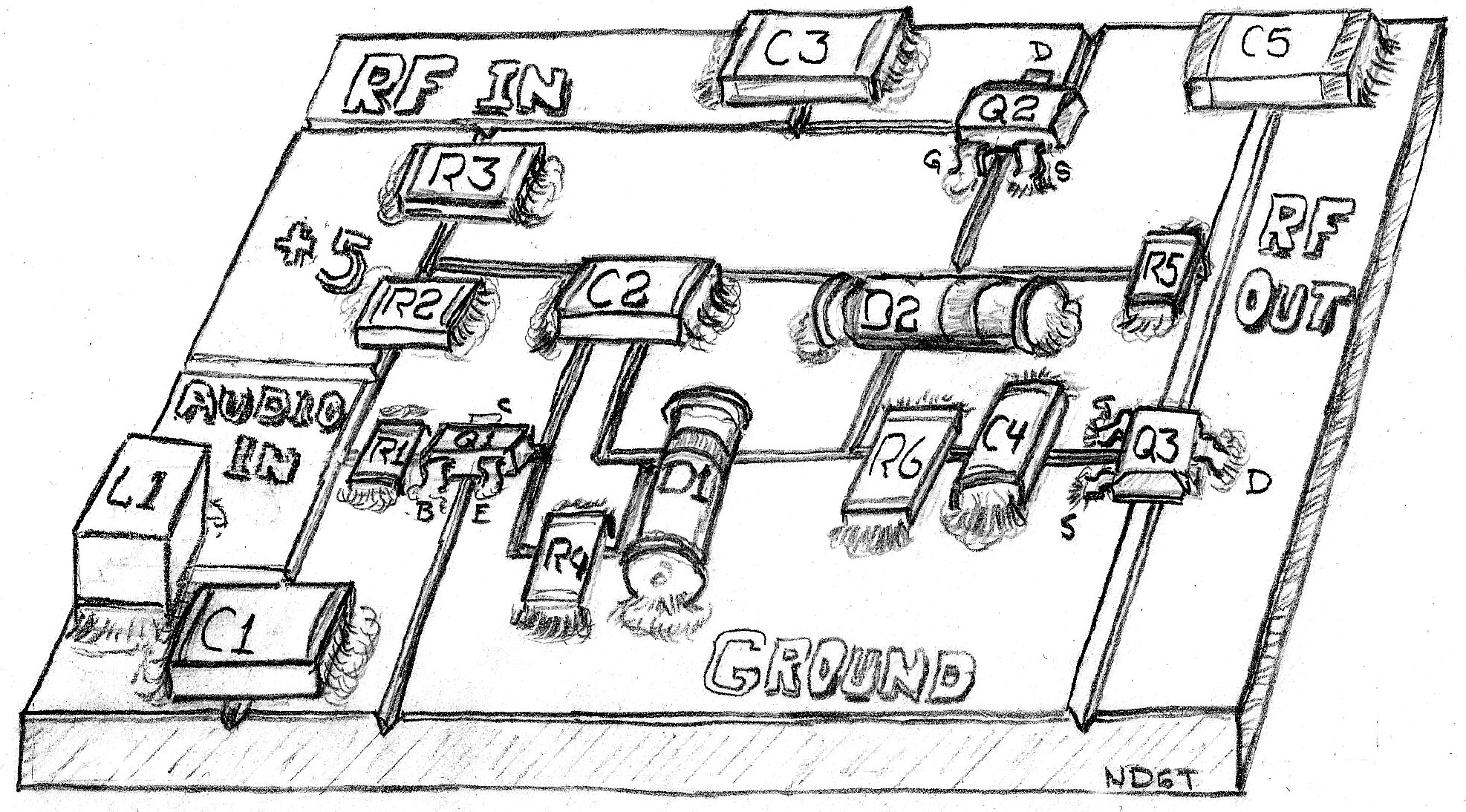
A spot of fast-setting glue holds the board to the back of the manual RF gain control. Remove the coax center conductor from the potentiometer wiper and connect it to the junction of Q3 drain and C5. Run a jumper from the wiper lug of the gain control and connect to the vacant pad of C3. Leaving the manual RF gain control in place will give you extra control should you wish it. Very short jumpers keep things solid and have purer control. Power can be supplied from any nearby 5 volt source (like pin 3 up on the Raduino, usually green wire). It just needs to be from 4 to 5 volts and only draws less than 2 milliamps.

If you want to add a switch to shut off the AGC, do so at the audio input. I would suggest a single-pole double-throw switch with the connection to C1 at the center, ground to one side, and the other to the hot side of the volume control. If power is removed from this circuit Q2 will not be biased “on” and will reduce signal levels significantly.

A good, solid ground is most important. I recommend a ground lug on the potentiometer shaft or on any other nearby ground point. A poor RF ground will yield poor attenuation. 40 dB is a ratio of 1 to 10,000! Hundredths of an ohm count.

If you don’t use an RF gain control

If you don’t have room for a manual RF gain control or a switch there is no reason to worry. This circuit can be left active and placed near the RF path connector without a problem. You could easily build this as a module that simply plugs into the connector. The most critical junction would again be a nearby ground but a third pin, this time through the board to the ground plane, would help. There should be little need to operate without it. If you need to run any tests that need it disabled, just remove the plug to the RF receive path and replace it with a shorting plug across the two RF pins.

If you adverse to surface mount construction, there is little problem in building it with leaded components. Use 2N7000 or BS170 MOSFETs and a 2N3904 or 2N2222 type NPN transistor. Try to keep wiring short and compact in the RF attenuator portion but the rest is very non-critical. If you use an electrolytic or tantalum capacitor for C4, observe polarity.

Parts List

  • 1: NPN switching transistor (1B, 2N3904, 2N2222) [Q1]
  • 2: N-channel enhancement mode MOSFET (2N7002, 2N7000, BS170) [Q2,3]
  • 2: Silicon switching diodes (1N4148, 1N914) [D1,2]
  • 2: 0.01 uF, 6 volt or higher ceramic capacitor [C3,5]
  • 2: 0.1 uF, 5 volt or higher ceramic capacitor [C1,2]
  • 1: 10 uF, 6 volt or higher ceramic (preferred) electrolytic, or tantalum capacitor [C4]
  • 1: 1 Kohm resistor [R2]
  • 4: 100 Kohm resistor [R1,3,4,5 ]
  • 1: 1 Mohm resistor [R6} (or other value, depending upon desired AGC recovery rate)

Explanation

Signals below 50 microvolts (S9) are unaffected. Above that level, the AGC begins to engage. Q2, the pass transistor, begins to turn off a bit while Q3, the shunt transistor, begins to turn on. Signals are attenuated to where the audio output is held to reasonable levels and the rest of the receiver does not experience distortion. If you are considering adding an S meter this circuit may be to advantage due to the amplifier stage. The control bias is available at the junction of D2,C4, Q2,R5 and R6. This is the spot that you would use for a metering source.

Conclusion

AGC makes for a much more pleasurable experience. Don seldom needs to reach for the RF gain control or the volume when an especially strong signal suddenly appears. During nets I can now wander about the shack and still hear all of the check ins. Round tables don’t require a hand on the controls. Things are getting easier.

Recommended by others

Tim AB0WR says, “I am using this new AGC circuit. It works well. You still get a slight pop when an extremely strong signal first comes on but it is very short and, to me at least, not annoying at all. You may want to lower the 1 M Ohm resistor to something smaller to decrease the pop i.e. decrease the attack time. The next time I open the case I’m going to try 500K.”

Jim W0EB says “Thanks ND6T for a very workable AGC circuit!”.

It is clear that this has become the new ubitx.net recommended AGC mod.

Reference

Using a 1N4004 or similar as a varicap or pin diode for AGC control

Allison KB1GMX finds it  odd that every one seems to be bent on levelling the audio volume in the audio circuit.

The Bitx or uBitx has enough gain and handy places that RF gain control based on audio detection works very well. The easy way is replace R13 (ubitx) with a diode such as 1n400x (x=1 to 7) and controlling the  current through the diode to make it behave as a variable resistance at RF.

The current would be about 4-6ma at max gain and decrease to zero (0) at minimum gain.  For that design the AGC range is about 26 to 32db depending on the band. If you feel that is not enough AGC range then add the same mod at R33 and with both the AGC range is near 60+ DB, generally enough.

AGC in this form is less prone to overload distortion as you are lowering gain. The control could be a pot between 8V (or RX-V) and ground and a series 1K resistor to the diode (x2 if using both diodes). That gives a manual gain control. To make it automatic use a circuit to detect the voltage at the top of the audio gain pot and feed that voltage to the gain control diodes. The circuit should be arranged to put 4-8V out at NO Audio and decrease to zero volts with increasing audio.

The 1n400x series with minor reservations makes a fine substitute for a PIN diode, the preferred but more costly device for this function. Beside being widely available and cheap  makes it useful.  It also makes a good 20pf varicap and a 1A rectifier to 1000V (1n4007).

This was tested on the first bitx20 that Allison built over a decade ago to test AGC.  It has been used on several older Tentec radios and more than few of her own design. That said its far from a new idea or design as its documented in EMRFD and an older book (Solid State Design, ARRL press, now out of print).

Jerry KE7ER climbs into the conversation saying:

“I have no idea what the capacitance of a slightly forward biased 1n400x is,
figure 6 here suggests it’s north of 30pf:    Therefore, it might be marginal at 45mhz, and can vary wildly with diode type and brand.

Consensus seems to be that a 1n4007 is preferred over other 1n400x flavors for use as a PIN.   Some experimentation may be required using diodes from different manufacturers:

If you are paying $5 postage to ship in some 1n4007’s, you might consider
also getting some BAP64-02’s at $0.43 each single unit pricing, Mouser 771-BAP64-02-T/R.  These are fully specified for use as an RF PIN diode.

Reference


Extensive VK2ETA mods to KD8CEC firmware

John, VK2ETA, has implemented a range of changes in Ian KD8CEC’s software targeted at portable operations (the software can be downloaded here in the files section of the BITX20 IO Group).

VK2ETA Software modifications to KD8CEC firmware

The scope of these modifications is described below:

Options for various features – These can be turned on or off. Key objective is to be able to customise the rig based on your needs and unfortunately on the restricted memory size of the Nano. So not all features can be selected at once. Choices, choices…

ATU control – A servo-based L-Network ATU. The communication between the Raduino and the ATU Arduino is via I2C. There is a separate sketch for the ATU Arduino (Nano or Pro-mini).   ATU operating mode can be set to OFF, Manual as in on-demand, or auto-RX meaning that it pre-tunes based on historical data on a change of band and after first change of dial frequency (for a quick scan of the bands). It uses the EEPROM data of the closest stored frequency for pre-tune or tune on-demand to accelerate the tuning process.

Handsfree microphone/headphone – Using an Android style 3 rings (TTRS) handsfree earpieces/mic combination, with 1 or 3 buttons (Play/Pause, +, -), the PTT is controlled by Play/Pause as toggle, and I use long presses on + and – as respectively pre-tune and smart-tune of the ATU. Short + or – presses could be used for frequency up and down. Requires a very simple hardware mod to free-up A6 (see below).

S-meter measure and display – using analogue input A7 from an 2N7002 based AGC or a MAX9814 circuit or any other for that matter.

Software based AGC range extender – to augment (as in double or triple) the dynamic range of an audio AGC. This uses the slope of the 1st If filter at 45Mhz to attenuate the Rx signal when the audio AGC reaches its limit. Adds over 50dB of dynamic range.

Forward power and SWR measure and display – Currently assumes that the ATU is providing that info over I2C. Otherwise could be adapted with a pair of analogue inputs for measure. See the excellent NT6D design on the wiki.

Options for displaying the S-Meter, SWR and forward power –  in either easy to see “fat” bars with no number, or “skinny” bars with more text and numbers.

Enable a “Memory mode” – selectable by menu, which cycles through all the populated memories (channels). Dial lock also locks the change of channels.

Made some rarely used or once-off functions as options  – to recover program memory after initial tuning and allow for more options to be selected.

Fixed some issues with the IF-shift option – Ian has resolved these in his new V1.06 and later releases. Two issues were present: IF-shift in USB would change the receive frequency and it was applied to TX as well. Now applies to Rx only.

Hardware modifications required to use VK2ETA software mod

The only required hardware mod is to connect the CW key input to the PTT. Since in Ian’s software we select the mode by menu, there is no need to have a separate analogue input tied-up for the CW key. This frees-up analogue input 6 for use by other functions like the handsfree option above.

Still to come

John plans to apply Ian’s improvements in v1.06, especially the CW transmit frequency option and if possible the WSPR beacon mode (as a further add-in option).

How to use VK2ETA software

Download the zip files, and unzip these in your Arduino sketches folder.  Edit the ubitx_20 options sections, using #define for enabled and #undef for disabled.

Perform a CTRL-R to compile and check how much memory is used. If you go over the limit, a warning is issued.  Providing you have enough memory to run the software, upload the sketch to the Arduino.

John has uploaded both the Raduino as well as the Arduino sketch for the ATU and SWR measurement. They can be found in the folder “Variations on Ian Lee’s Software (by VK2ETA) + ATU sketch”. 

All software is released under GPL V3.
Reference

Use the 45MHz Roofing Filter for an RF AGC?


John, VK2ETA, came across an idea in the search for a greater range for his MAX9814 AGC circuit.

Stations, above S9+10 would produce distortion in the audio circuit with the MAX9814 AGC in circuit.   He isolated this to the MAX circuit as the distortion would disappear when it was bypassed.

John was curious as to what the first 45Mhz filter (Roofing Filter) shape was like and if there was some plateau to be used somewhere for attenuating the strong signals.

He modified Ashhar Farhan’s original software to include an “Adjust First IF” menu item, in steps of [1000Hz].

By using a local station’s carrier aligned on 1,500Hz audio as a reference and an Android audio spectrum display he plotted the response of the single crystal roofing filter. This also gave an idea of the effect on the audio of shifting the filter up and down. The “noise” in the graph below near the peak is the effect of changing from a measure every [10,000Hz] to a measure every [1000Hz], plus the inaccuracy of John’s rudimentary instrumentation.

As you can see, there are rather slow slopes on each side of the peak (which is off-center by [7,000Hz] approximately when compared to 1,500Hz – the centre frequency of an SSB signal).

So John has proceeded with changing Ian’s software (based on v1.04) to incorporate an automatic AGC step-down when the signal reaches S9+10 and and automatic step-up when it reached S0. In the middle range, the MAX audio circuit does the AGC job.

John used the up side of the filter as he got some birdies on some of the shifts on the down side.

Now the uBitx can handle S9++++ stations with ease, that is until the first amplifier stage before the filter saturates which John suspects is unlikely in “normal” conditions.

The only concern would be for another, possibly even stronger, station which would be placed at the peak of the filter (possibly several KHz away). This could produce intermod distortion. But the chances of that happening are pretty remote.

So, this approach works quite well and is surprisingly effective for AGC control at an early stage in the receiver.

It also works in reverse, with the transmit SSB signal being attenuated by the same amount, thereby leading to a possible ALC software control for the units which measure the power out (or possibly just the current).   It could also be a simple solution to set attenuation (e.g. on digital modes).  Again, check the effect of the slope on the voice tone.

John has attached snippets of his code.  He has also uploaded the modified uBitx software for testing the filter both in RX and TX in the  “Software based IF attenuation” folder in the BITX20 IO Group files.

John will soon publish the complete set of Ian’s modified software including mods to control his ATU unit.   However, in seeing discussions on an IF AGC in the group, he thought this update would be of interest to constructors.

Code Snippets

#define OPTION_SMETER
#define OPTION_SOFTWAREAGC

void doSoftwareAGC() {
#ifdef OPTION_SMETER

int newSMeter;

//VK2ETA S-Meter from MAX9814 TC pin
newSMeter = analogRead(ANALOG_SMETER);
//Serial.print(“newSMeter:”); Serial.println(newSMeter);

//Faster attack, Slower release
currentSMeter = (newSMeter > currentSMeter ? ((currentSMeter * 3 + newSMeter * 7) + 5) / 10 : ((currentSMeter * 7 + newSMeter * 3) + 5) / 10);

//Serial.print(“currentSMeter:”); Serial.println(currentSMeter);
//Scale it
scaledSMeter = 0;
for (byte s = 8; s >= 1; s–) {
if (currentSMeter > sMeterLevels[s]) {
scaledSMeter = s;
break;
}
}
//Serial.print(“scaledSMeter, un-adjusted:”); Serial.println(scaledSMeter);
#ifdef OPTION_SOFTWAREAGC
//Apply auto-shift of first IF to increase the dynamic range of the Audio AGC circuit
long previousShift = firstIfShift;
if (scaledSMeter >= 7) {
//Reduce gain by shifting the first and second If by the same value, thereby
// leaving the RX frequency the same but using the slope of the roofing
// filter to deliver progressive attenuation.
// 10kHz or 5kHz per step.
firstIfShift += (scaledSMeter > 7 ? 10000 : 5000);
} else if (firstIfShift > 0 && scaledSMeter < 1) {
//Re-increase the gain if we reduced it earlier
firstIfShift -= 5000;
firstIfShift = firstIfShift < 0 ? 0 : firstIfShift;
}
if (firstIfShift != previousShift) {
setFrequency(frequency);
//Serial.print(“firstIfShift:”); Serial.println(firstIfShift);
//Adjust meter by IF attenuation except for the first 10Khz. Approx 6dB per 5KHz.
scaledSMeter += (firstIfShift > 10000 ? (firstIfShift – 10000) / 5000 : 0);
//Serial.print(“scaledSMeter, adjusted:”); Serial.println(scaledSMeter);
}
#endif //OPTION_SOFTWAREAGC
#endif //OPTION_SMETER

}

//And the setfrequency function becomes:

void setFrequency(unsigned long f) {
f = (f / arTuneStep[tuneStepIndex – 1]) * arTuneStep[tuneStepIndex – 1];

setTXFilters(f);

if (cwMode == 0)
{
if (isUSB) {
//si5351bx_setfreq(2, SECOND_OSC_USB – usbCarrier + f + (isIFShift ? ifShiftValue : 0));
si5351bx_setfreq(2, SECOND_OSC_USB + firstIfShift – usbCarrier + f – ((isIFShift && !inTx) ? ifShiftValue : 0));
si5351bx_setfreq(1, SECOND_OSC_USB + firstIfShift);
}
else {
//si5351bx_setfreq(2, SECOND_OSC_LSB + usbCarrier + f + (isIFShift ? ifShiftValue : 0));
si5351bx_setfreq(2, SECOND_OSC_LSB + firstIfShift + usbCarrier + f + ((isIFShift && !inTx) ? ifShiftValue : 0));
si5351bx_setfreq(1, SECOND_OSC_LSB + firstIfShift);
}
//VK2ETA Bring back the BFO to default if using IF Shift and we are TXing
si5351bx_setfreq(0, usbCarrier + ((isIFShift && !inTx) ? ifShiftValue : 0));
}

else
{
if (cwMode == 1) { //CWL
//si5351bx_setfreq(2, SECOND_OSC_LSB + cwmCarrier + f + (isIFShift ? ifShiftValue : 0));
si5351bx_setfreq(2, SECOND_OSC_LSB + firstIfShift + cwmCarrier + f + ((isIFShift && !inTx) ? ifShiftValue : 0));
si5351bx_setfreq(1, SECOND_OSC_LSB + firstIfShift);
}
else { //CWU
//si5351bx_setfreq(2, SECOND_OSC_USB – cwmCarrier + f + (isIFShift ? ifShiftValue : 0));
si5351bx_setfreq(2, SECOND_OSC_USB + firstIfShift – cwmCarrier + f – ((isIFShift && !inTx) ? ifShiftValue : 0));
si5351bx_setfreq(1, SECOND_OSC_USB + firstIfShift);

}
//VK2ETA Bring back the BFO to default if using IF Shift and we are TXing
si5351bx_setfreq(0, cwmCarrier + ((isIFShift && !inTx) ? ifShiftValue : 0));

}

Reference

An S-Meter and AGC circuit

Don ND6T has recently installed a 20 dB RF AGC modification in the BITX40.

He has not installed it in the uBITX yet but intends to do so soon.   It’s a simple circuit and replaces the S meter circuitry, too.

Most BITX automatic gain control schemes use the audio output to apply control of the input of the audio power amplifier. This depends upon the volume control setting and introduces considerable distortion on high level signals. By using a signal source before the control then we can use the constant fixed gain of the receiver as a good indicator of signal strength and still adjust the speaker or headphone levels for the best comfort.

This simple project uses a single stage amplifier to tap into the audio at the input of the volume control, rectify it to a DC level, filter it, and use it to control a MOSFET as a shunt across the receive RF path. This project assumes that you have already installed the RF gain control described here (for the BITX40 or here (for the uBITX) and bridges across it at the control potentiometer.

R3 and C3 are used to not only filter out the audio component, but to form a “fast attack, slow release” control signal. That means that, when a strong signal appears, RF gain will be quickly reduced but will take a second or so to restore to full gain after the signal stops. This avoids “pumping” during a single sideband transmission but is fast to react to very loud signals.

Nearly any general purpose NPN bipolar junction transistor will work as Q1 as long as it has a beta of more than 100. 2N2222, 2N3904, etc. will work quite well. Q2 can be a 2N7000 or a BS170. None of the component values are critical. The 5 volt supply makes it easy to use any part with more than a working limit of just 6 volts and the current drain is low enough to be negligible.

I have found that most 2N7002 transistors will yield at least 20 dB of RF attenuation across the HF spectrum at 50 ohm impedance. Attenuation begins around 1.4 volt bias on the gate referenced to the source and provides maximum action at around the 3.7 volt level. Very effective for a single, simple, and inexpensive device. A great first step.

A more fulsome article with construction details (using surface mount components) is posted on nd6t.com.

This simple circuit led to a discussion on the BITX20 IO Group list, started by Jerry KE7ER, about the BAP64Q pin diode attenuator.   This gives 60dB of dynamic range:  https://groups.io/g/BITX20/message/32066

Attenuating back in RF gets around the limited dynamic range that Henning points out in the first post of that thread.    Note that the control voltage is inverted with respect to the 2n7002 FET, higher voltages give less attenuation.   You could get a slightly lower noise figure for the receiver if the attenuator was inserted at a later stage of the RF chain.

Jerry observes, “The BAP64Q is relatively expensive at $0.50 single piece,
the frugal among us will note it’s down at $0.20 if you buy a few thousand.
Mouser and Digikey both stock it, Mouser points you to the wrong BAP64* datasheet.   There are other similar small signal pin diode attenuators out there from other manufacturers.”

Reference

AGC Mod

Challenges with AGC circuits

Finding an AGC mod that works, and works well (with sufficient AGC range, that does not impact on the dynamic range of the receiver, and that does not distort) is proving to be difficult.  Nobody has probably tried out more AGC mods than John VK2ETA.

See his thread here for his experiences with a range of AGC mods.

MAX 9814 Circuit

John VK2ETA has now settled on using the MAX9814 circuit for his AGC.

He used the Adafruit MAX9814 board but there are a few variations on eBay with some probably requiring less hacking than the Adafruit design. John had to solder a wire on an SMD component to access the CT (time constant capacitor) pin of the MAX IC, and remove the Electret capsule.

Refer to the schematic and a few pictures of the AGC circuit. The 5VDC required for the Adafruit board is taken from the Raduino.

John took two sets of measures, one with the AGC turned down low and one with the AGC turned one third of the way up.

He used an A/B comparison with an FT-817, with the pre-amp off, receiving  a carrier at 1,500Hz from local radio stations (with attenuation). The FT-817 S-Meter seem non-constant in the steps between the S-units, but nevertheless, this was John’s reference for calibrating the AGC. The AGC voltage was taken on the CT pin of the MAX9814.

The AGC voltage fluctuates quite a lot, so he used the average value shown over time.

To determine whether any saturation was coming from the AGC circuit or the uBitx upstream at high signal strengths, he would bypass the AGC and keep the volume down to prevent the audio circuit after the volume pot from saturating. If harmonics of the audio disappeared, the AGC alone was producing distortion, otherwise it appeared at least prior to the AGC, and possibly from the AGC circuit as well.

Results

“Medium” AGC: input pot turned to about 30% of full scale.

FT817         AGC
S-Meter     voltage(mV)       Notes
S0                  0
S1               300
S2               350
S3               400
S4               460
S5               510
S6               650
S7               750
S8             1,700          Large variation. FT-817 S-meter S8 plateau issue?
S9            2,200          Some saturation of AGC noted (starts to appear in audio FFT, not noticeable)
S9+10     2,460           Saturation of AGC audible, but not unpleasant.
S9+20     2,460          Audible saturation of both uBitx and AGC (harsh sound).

The AGC kicks in early and keeps the volume pretty constant until saturation occurs. Saturation of AGC does limits the dynamic range of receiver.

“Low” AGC: input pot turned to about 7-10% of full scale.

FT817          AGC
S-Meter      voltage (mV)       Notes
S0 -S4               0
S5                50-200                  (100mv avg)
S6                  200
S7                  360
S8                  500
S9                1,260
S9+10         1,800
S9+20         2,300                 Saturation of both uBitx and AGC  (visible in audio FFT, but not really audible)
S9+30         2,400                 Audible saturation of uBitx and mostly of AGC.

This is the most “FT-817 AGC” like, from my perspective, and is what I have settled for.  I want to use the AGC voltage as an s-meter input and this setting does produce a gap at the bottom end, but this is not critical IMO.

In both cases I noted some small “clicks” when the AGC kicked in on strong sudden signals.

The maximum gain of the MAX9814 as set in the schematic attached is of 50dB and requires screened cables in the audio circuit. I originally had the input and output of the circuit fed to a two core “stereo” screened cable and I would get feedback. I had to use two single screened audio cables.

Reference

SSM2166 (Mic amplifier and compressor) as Audio AGC?

Henning Weddig DK5LV says he is in the process of using an op amp and SSM2166  on his “original” BITX40 as a way of achieving an audio AGC function.

This op amp has a  gain of 10 (20 dB) and an audio AGC system.   He purchased a pcb from ZL1CVD with the DIL chip via ebay years ago.  Unfortunately ZL1CVD does not sell this pcb any more…

The SSM2166 has a dynamic range of 60 dB, the opamp in front of it is intended to replace the first discrete amplifier after the demodulator and will amplifiy the audio into a range the SSM2166 can handle.  The SSM2166 has a provision for outputting an AGC voltage (an RMS output) and this may be able to be used for driving an S-meter.

Others are thinking along the same lines.  For example, Glenn VK3PE says:

“I’m thinking along the same lines. I built a Mic amp version using the SSM2167 and thought it might work also for the Receiver. It’s essentially the module seen on ebay but I’ve added a level pot on the output side.”

Meanwhile Alex PA1FOX comments:

“I am using the AGC from the original uBitx design, but found the time constant of 1uF and 100k to be far too low. This makes it a very fast AGC, not producing a nice sound with voices. I changed to 1.5 uF and 4M7 and now stronger stations are nice and clear (they ‘push’ the noise level down ) and the gain comes up nice and easy when the QRG is clear. I think I’ll keep it this way.”

Reference

An RF based AGC design from K P S Kang

K P S Kang VU2KR / VU2OWF has an item on his blog showing an RF AGC for BITx designs.  The AGC is apparently very effective at calming those 9+20dB signals that on the uBITx will damage your hearing!

The design is for the BITx40, but can be readily adapted for the uBITx – probably not at the antenna (because it is best to avoid diodes at the front end of the uBITx), but at the 45MHz IF stage.  Are there any takers to adapt this design for the uBITx?

AGC for uBITx controlled by I2C via Software

Nick VK4PLN admits he has tried just two AGC approaches on BITx rigs: the VK3YE AGC (which is shall we say very illuminating) and the ADAFRUIT TPA2016 I2C module.

Nick found the VK3YE solution messed with the audio quality, made it all scratchy, and still didnt handle local 100w stations well …

Now after playing with the TPA for a few days he is very happy with the results.  Audio has good depth and AGC is responsive, and the unit also gives a nice increase in gain.

One trick for others who want to implement this,  is that you will need to add some code to the Adafruit library to implement the enableNoiseGate(false); function.    We need to turn the NoiseGate off or else the AGC will not ramp up with only background noise and you will not hear anything until a loud signal comes on.  [EDITOR notes that this could be used as a kind of SQUELCH function].

Also the speaker output is NOT grounded, you need to isolate your SPEAKER jack so that the – ve line from the TPA2016 is direct to the speaker with no chassis grounding…   Output from the amplifier can’t be fed into another amplifier.

The Best part in Nick’s opinion is that all of the AGC related settings are customisable if you want.  If not, just use the voice settings from the datasheet.   Nick says the defaults work great!

Stereo 2.8W Class D Audio Amplifier – I2C Control AGC – TPA2016

Nick says he will post the code to the list along with a few pics… This extra info should appear here shortly.

REFERENCE

And the board installed in Nick’s uBITx can be seen below.  It looks a real tidy build!

Software

Nik has now shared his software:

/*************************************************************************
VK4PLN’s AGC Code. Adafruit TPA2016
Add call to setupTPA2016(); to main code setup() in ubitx_20 after initOscillators();
**********/

#include <Wire.h>
#include “Adafruit_TPA2016.h”

Adafruit_TPA2016 audioamp = Adafruit_TPA2016();

void setupTPA2016() {

audioamp.begin();
// See Datasheet page 22 for value -> dBV conversion table
// Serial.println(“Right off, Left On,”);
audioamp.enableChannel(false, true);

// Noise Gate Threshold: Below this value, the AGC holds the gain to prevent breathing effects.
//Select the threshold of the noise gate (1,4,10,20mV) (0-3)
// Serial.println(“Noise Gate Threshold,”);
//Disable NoiseGate, we want to hear everything, even weak signals….
audioamp.enableNoiseGate(false);
audioamp.setNoiseGateThreshold(0);

// Fixed Gain: The normal gain of the device when the AGC is inactive.
// The fixed gain is also the initial gain when the device comes out of shutdown mode or when the AGC is disabled.
// value 6 seems to work ok… based on datasheet. Where gain is from -28 (dB) to 30 (dB)
// Serial.println(“Setting Fixed Gain”);
audioamp.setGain(-12); //-27 is ok? -12 is too high local stations arnt clipped…

// Compression Ratio: The relation between input and output voltage.
// AGC can be TPA2016_AGC_OFF (no AGC) or
// TPA2016_AGC_2 (1:2 compression)
// TPA2016_AGC_4 (1:4 compression) * Datasheet – Voice
// TPA2016_AGC_8 (1:8 compression)
// Serial.println(“Setting AGC Compression”);
audioamp.setAGCCompression(TPA2016_AGC_8);

// Limiter Level: The value that sets the maximum allowed output amplitude.
// Serial.println(“Setting Limit Level”);
audioamp.setLimitLevelOn();
// or turn off with
//audioamp.setLimitLevelOff();
audioamp.setLimitLevel(30); // range from 0 (-6.5dBv) to 31 (9dBV) (8.5dBv(30) as per datasheet)

//Maximum Gain: The gain at the lower end of the compression region
// Serial.println(“Setting AGC Max Gain (18-30db – (0-12)”);
audioamp.setAGCMaxGain(12);

/*
* For voice systems the attack time should be in the 2-ms region, with a hang time of about 0.3 sec,
* followed by a gradual recovery time of up to 1 sec.
* http://www.qsl.net/va3iul/Files/Automatic_Gain_Control.pdf
*
*/

// See Datasheet page 23 for value -> ms conversion table
// Serial.println(“Setting AGC Attack (0.1-6.7ms – (0-63))”);
audioamp.setAttackControl(3);

// See Datasheet page 24 for value -> ms conversion table
// Serial.println(“Setting AGC Hold (0.0137-0.8631ms – (1-63))”);
audioamp.setHoldControl(0);

// See Datasheet page 24 for value -> ms conversion table
// Serial.println(“Setting AGC Release (0.0137-0.8631ms – (0-63))”);
audioamp.setReleaseControl(4);

}

Also, need to add this new function to Adafuit library after the existing enableChannel function:

// Turn on/off Noise Gate
void Adafruit_TPA2016::enableNoiseGate(boolean ng) {

uint8_t setup = read8(TPA2016_SETUP);
if (ng)
setup |= TPA2016_SETUP_NOISEGATE;
else
setup &= ~TPA2016_SETUP_NOISEGATE;

write8(TPA2016_SETUP, setup);
}

And the line for the header file:

void enableNoiseGate(boolean ng);

in .h file:
void setNoiseGateThreshold(uint8_t thresh);

in .cpp file

void Adafruit_TPA2016::setNoiseGateThreshold(uint8_t thresh){ //Added by VK4PLN
if (thresh > 3) return; // max threshold is 3 (20mV)
uint8_t agc = read8(TPA2016_AGCLIMIT);
  agc &= ~(0x20);  // mask off bottom 5 bits
  agc |= thresh;        // set the limit level.
  write8(TPA2016_AGCLIMIT, agc);
}
Reference

BITx AGC kit

David N8DAH has assembled AGC kits for BITx transceivers.  These were designed for the BITx20 and BITx40, but should work fine in the uBITx.

The AGC design was posted on DuWayne KV4QB’s site found here and used with permission. All kits will come with:

  • PCB x 1
  • Parts placement layout x 1
  • 2N3904 x 1
  • 2N7000 x 1
  • 47uf x 2
  • 1N4148 x 1
  • 100R x 3
  • 100k x 3
  • 10k x 1 this is extra for the user to play with attack or input values.
  • 2k2 x 1
  • .1uf x 2 unmarked tan

Missing parts will be replaced.   

This is the 3rd run of the boards.  Many group members have this AGC already in use.

Cost and options:

#1 – Kits 13$ shipped

#2 – Pre-built OT service 15$ shipped and tested

Write to David if you want to reserve a kit.

Reference

NB these are sold out as of 29 January 2018.